Siemens P1 BIM Скачать руководство пользователя страница 4

Document No. 553-140 
Installation Instructions 
November 4, 2019 

Unrestricted Information in this document is based on specifications believed correct at the time of publication. The right is reserved to make 
changes as design improvements are introduced. APOGEE and Insight are registered trademarks of Siemens Industry, Inc. Other product or 
company names mentioned herein may be the trademarks of their respective owners. © 2019 Siemens Industry, Inc.


Siemens Industry, Inc. 

Smart Infrastructure 
1000 Deerfield Parkway 
Buffalo Grove, IL 60089-4513 
+1 847-215-1000 

Your feedback is important to us. If you have 
comments about this document, please send them 
to [email protected]

Document No. 553-140 

Printed in the USA 

Page


4 of 4


Configuring the 4-Module P1 BIM 

1.  Power up the P1 BIM. 

2. 

Plug in the USB on both ends (the device side to 
the P1 BIM; the host side to the computer). 

The device will be automatically recognized and 
installed. 

3. 

Open Windows Explorer. 

4. 

Find the USB device/drive (will say SIEMENS 
P1BIM Configuration Tool) in the drives list. 

5.  Open the drive. 

6.  Double-click 

P1BIMCFG.exe

 to launch the 

application. 

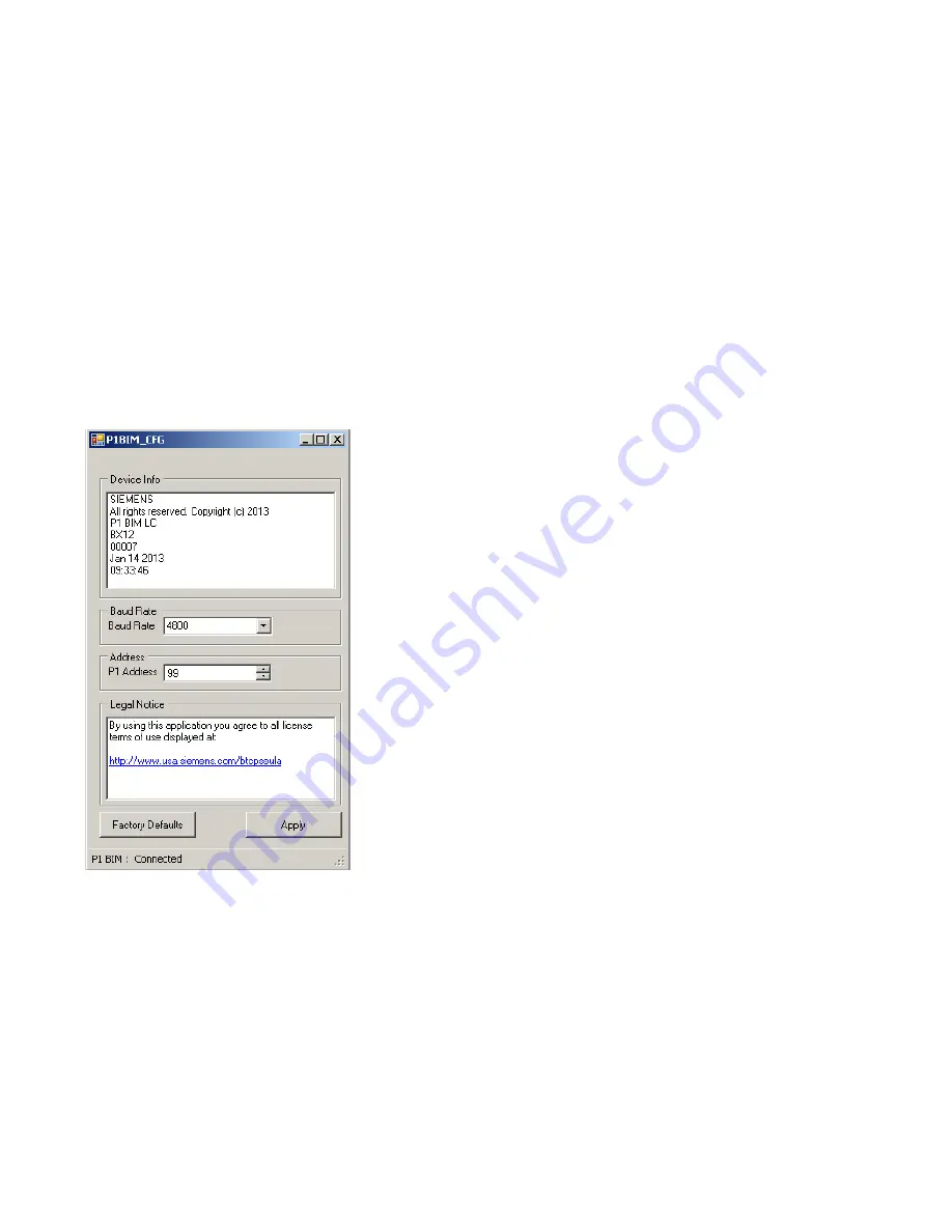
The following dialogue box displays: 


7.  Select the desired Baud Rate from the drop-down 

menu. (Note: Only 4800 and 38400 are supported 
rates.) 

8.  Click 

Apply

9.  Verify that the baud rate you selected is displayed 

in the 

Baud Rate

 field. 

10.  Enter the desired address in the 

P1 Address

 field. 

The default address is 99, but the device will not 
communicate if left at the default address. Valid 
P1 addresses are 1 through 98. 

11.  Click 

Apply

.  

12.  Verify that the address you entered is displayed in 

the P1 Address field. 


Содержание P1 BIM

Страница 1: ... as specified CAUTION Equipment damage or loss of data may occur if you do not follow a procedure as specified Required Tools and Materials Wire stripper side cutter Small flat blade screwdriver Digital multimeter DMM Expected Installation Time 7 minutes Prerequisites CAUTION No power wiring is connected to the field panel controller or other TX I O components at this time CAUTION The TX I O islan...

Страница 2: ...us System Neutral must be connected to building approved earth ground at a single point only at the 24 Vac transformer Installation CAUTION Turn OFF AC power at the ON OFF switch in the Service Box or transformer enclosure CAUTION UL Listings require that NEC Class I and Class II wiring be kept separate from each other Use separate conduit and cable tie bars to separate Class I Digital Output DO w...

Страница 3: ...X I O island bus connector 5 Push in each mounting tab until it clips onto the DIN rail Connecting Devices to the TX I O Island Bus Completing the Installation CAUTION For RS 485 ALN or FLN terminate only one end of the shield wire on the enclosure earth ground For a 3 wire system terminal is connected to reference wire Protective ground terminal may be connected to earth ground For a 2 wire syste...

Страница 4: ...ed in the USA Page 4 of 4 Configuring the 4 Module P1 BIM 1 Power up the P1 BIM 2 Plug in the USB on both ends the device side to the P1 BIM the host side to the computer The device will be automatically recognized and installed 3 Open Windows Explorer 4 Find the USB device drive will say SIEMENS P1BIM Configuration Tool in the drives list 5 Open the drive 6 Double click P1BIMCFG exe to launch the...

Отзывы: