background image

GBB/GIB Series Non-spring Return, 24 Vac, Modulating Control 

Technical Instructions  


Document Number 155-176P25 


June 22, 2015 

Siemens Industry, Inc.  

Page 13 


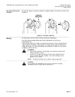
Reversing the Position 
Indicator 

Reverse the position indicator so that the counterclockwise 0 to 90 scale is visible.


See 

Figure 27. 


Figure 27.  Position Indicator. 

Wiring 

All wiring must conform to NEC and local codes and regulations. 

Use earth ground isolating step-down Class 2 transformers. Do not use 
autotransformers. 

The maximum rating for a Class 2 step-down transformer is 100 VA. Determine the 
supply transformer rating by summing the VA ratings of all actuators and all other 
components used. It is recommended that one transformer power no more than 10 
actuators (or 80% of its VA). 


WARNINGS: 


Mixed switch operation is not permitted to the switching outputs of both 
auxiliary switches (A and B). 


Either AC line voltage from the same phase must be applied to all six 
outputs of the dual auxiliary switches, or UL-Class 2 voltage must be 
applied to all six outputs. 

NOTE: 

With plenum cables, only UL-Class 2 voltage is permitted. 


CAUTION:


Do not parallel wire GBB/GIB with any other type of actuator, including 
GBB/GIB actuators with date codes earlier than 501

Содержание OpenAir GBB Series

Страница 1: ...le dual auxiliary switches available UL cUL and CE listed Product Numbers Table 1 24 Vac Operating Voltage Torque Input Signal Cabling Standard Span Offset Adjustable Dual Auxiliary Switches and Span Offset Adjustable Dual Auxiliary Switches only 221 lb in 25 Nm 0 to 10 Vdc Standard GBB161 1U GBB163 1U GBB164 1U GBB166 1U Plenum Cable GBB161 1P GBB163 1P GBB164 1P GBB166 1P 310 lb in 35 Nm 0 to 10...

Страница 2: ...rrent DC 1 mA Equipment Rating Operating voltage input signal and Class 2 in accordance with UL CSA position output signal Plenum type actuators as a whole device Class 2 in accordance with UL CSA Auxiliary Features Dual auxiliary switches AC rating standard cable 24 to 250 Vac AC 6A resistive AC 2A general purpose AC rating Plenum cable 24 Vac AC 4A resistive AC 2A general purpose DC rating Stand...

Страница 3: ... See Figure 18 NEMA 3R rated when installed with ASK75 1U Weather Shield in the vertical position See Accessories IP54 according to EN60529 Material Die cast aluminum alloy Gear lubrication Silicone free Ambient Conditions Ambient temperature Operation 25 F to 130 F 32 C to 55 C Storage and transport 40 F to 158 F 40 C to 70 C Ambient humidity non condensing 95 rh Agency Approvals UL listed to UL8...

Страница 4: ...should be used with louvers and vents and in applications where use of the floor mount kit is not possible Kit contains Crank arm that changes the angular rotation into a linear stroke Support bearing ring to minimize side loading on the actuator s output bearing Mounting bracket Required mounting fasteners Figure 3 Crank Arm Kit ASK71 3 Kit allows a direct coupled actuator to provide an auxiliary...

Страница 5: ...0 mm shorter than the height of the self centering shaft adapter 985 052P20 Small shaft insert package of 20 when using the GIB actuator on a damper shaft less than 3 4 inch 20 mm diameter Figure 7 NEMA 3R Weather Shield ASK75 1U GBB and GIB Actuators are UL listed to meet NEMA 3R requirements a degree of protection against rain sleet snow and damage from external ice formation when installed with...

Страница 6: ...y 985 106 Provides protection for GIB GBB and GCA OpenAir actuators in an outside low temperature Assembly includes Weather Shield ASK75 1U Heater Kit 985 105 Figure 10 Conduit Adapter 985 008 1 2 inch 12 mm for 1 2 inch NPT connector Service Parts Figure 11 Position Indicator Figure 12 Standard Shaft Adapter Figure 13 Anti rotation Mounting Bracket 985 003 package of 10 985 004 985 006 ...

Страница 7: ... Components of the Modulating Actuator Legend 1 Positioning scale for angle of rotation 2 Span adjustment 3 Offset start point adjustment 4 Direction of rotation arrow 5 Connection cables 6 Manual override 7 Auxiliary switch B 8 Auxiliary switch A 9 Position indicator 10 Self centering shaft adapter 11 Shaft adapter locking clip 12 Position indicator adapter 13 Mounting bracket ...

Страница 8: ...he 0 position In the event of a blockage in the damper the actuator is overload protected over the full range to prevent damage to the actuator Life Expectancy An improperly tuned loop will cause excessive repositioning that will shorten the life of the actuator Control Signal Adjustment GBB GIB 163x GBB GIB 164x The offset start point and span of the control signal can be adjusted The offset poin...

Страница 9: ...l Umax maximum control signal Figure 16 Example Dual Auxiliary Switch GBB GIB 164x and GBB GIB 166x Actuator Scale Clockwise Adjustment range for Switches A and B Setting interval 5 Switching hysteresis 2 Actuator Scale Counterclockwise NOTE The auxiliary switch setting shafts turn together with the actuator The scales are valid only when the actuator is in the 0 position on clockwise motion To ch...

Страница 10: ...ng and Installation Figure 18 Acceptable NEMA 2 Positions Figure 19 Acceptable NEMA 2 Position for Tandem Applications The direction of rotation switch must be set to match the clockwise or counterclockwise rotation of the damper shaft The factory setting is clockwise See Figure 14 for location on the actuator Figure 20 Direction of Rotation Switch The minimum damper drive shaft length is 3 4 inch...

Страница 11: ...uators are to be used in tandem applications Manual override To move the damper blades when power is not present 1 Hold down the PUSH button 2 Make adjustments to the damper position 3 Release the PUSH button NOTE If there is no load the actuator will hold the new damper position If load conditions exist the actuator might not be able to hold Once power is restored the actuator returns to automate...

Страница 12: ...position indicator to the 0 position on the outside scale See Figure 25 Counterclockwise to open a Insert the shaft adapter to the left as close as possible to the raised stop b Hold down the PUSH button and rotate the shaft adapter to the right until it stops c Release the PUSH button d If the shaft adapter is not resting against the right raised stop remove the adapter and insert it against the ...

Страница 13: ... 2 step down transformer is 100 VA Determine the supply transformer rating by summing the VA ratings of all actuators and all other components used It is recommended that one transformer power no more than 10 actuators or 80 of its VA WARNINGS Mixed switch operation is not permitted to the switching outputs of both auxiliary switches A and B Either AC line voltage from the same phase must be appli...

Страница 14: ...e 2 Table 2 Wire Designations Standard Symbol Function Terminal Designations Color 1 Supply SP G Red 2 Neutral SN G0 Black 8 0 to 10 Vdc Y Gray 9 Output for 0 to 10 Vdc position indication U Pink S1 Switch A Common Q11 Gray red S2 Switch A Normally Closed Q12 Gray blue S3 Switch A Normally Open Q14 Gray pink S4 Switch B Common Q21 Black red S5 Switch B Normally Closed Q22 Black blue S6 Switch B No...

Страница 15: ...haft coupling returns to the 0 position 5 Check the Auxiliary Switch A a Set the DMM dial to ohms resistance or continuity check b Connect wires S1 and S3 to the DMM The DMM should indicate open circuit or no resistance c Apply a full scale input signal to wire 8 gray The DMM should indicate contact closure as the actuator shaft coupling reaches the setting of switch A d Connect wires S1 and S2 to...

Страница 16: ...heck that offset start point and span are set correctly if used Check that the direction of rotation switch matches the rotation of the damper shaft Connect wires 1 red and 2 black to a Digital Multimeter DMM with the dial set at Vac to verify that the operating voltage is within range If the actuator is not working check the damper for blockage If blocked remove the obstacle and cycle the actuato...

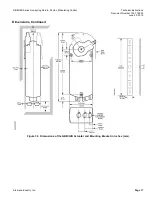
Страница 17: ...g Return 24 Vac Modulating Control Technical Instructions Document Number 155 176P25 June 22 2015 Siemens Industry Inc Page 17 Dimensions Continued Figure 30 Dimensions of the GBB GIB Actuator and Mounting Bracket in Inches mm ...

Страница 18: ...in may be the trademarks of their respective owners 2015 Siemens Industry Inc Siemens Industry Inc Building Technologies Division 1000 Deerfield Parkway Buffalo Grove IL 60089 USA 1 847 215 1000 Your feedback is important to us If you have comments about this document please send them to sbt_technical editor us sbt siemens com Document No 155 176P25 Printed in the USA Page 18 Dimensions continued ...

Отзывы: