background image

14
Smart Infrastructure

A6V11986596_en--_e

Building Products

2022-04-27

Technical data

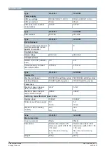
Type

N 545D31

N 543D51

Power supply

KNX bus voltage

DC 24 V (DC 21...30 V)

DC 24 V (DC 21...30 V)

KNX bus current

15 mA

20 mA

KNX power loss (internal
consumption)

0.15 W

0.17 W

Type

N 545D31

N 543D51

KNX medium

TP1-256

TP1-256

Type

N 545D31

N 543D51

Drive channels

2 relay contacts per channel,
electromagnetically locked
against one another

4

8

Contact voltage

Rated voltage

230 V AC

230 V AC

Contact current

Rated current, AC (resistive
load)

6 A

6 A

Current sensing for travel
time determination

≥ 75 mA

≥ 75 mA

Type

N 545D31

N 543D51

Service life

Mechanical lifespan

50,000,000 switching cycles

50,000,000 switching cycles

Electrical lifespan

100,000 switching cycles

100,000 switching cycles

Power loss

Maximum power loss per
device at rated output

2.8 W

5.5 W

Maximum power loss per
output at rated output

0.66 W

0.66 W

Switching capacities/load types, loads

Resistive load

1380 W

1380 W

Minimum switching capacity

5 V

10 mA

5 V

10 mA

Maximum DC1 breaking
capacity

30 V

6 A

30 V

6 A

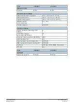
Type

N 545D31

N 543D51

Mechanical data

Housing material

Plastic

Plastic

Dimensions

Rail-mounted device in N
dimension, width 4 TE (1 TE
= 18 mm)

See 

dimension drawing

[

}

 16]

Rail-mounted device in N
dimension, width 8 TE (1 TE
= 18 mm)

See 

dimension drawing

[

}

 16]

Weight

246 g

450 g

Содержание N 543D31

Страница 1: ...connecting and looping through solid stranded and fine stranded conductors Every L conductor connection feeds two channels Functions for configuration with ETS Extensive control and override functions and status messages for each channel On site control of the drives Direct moving to element or slat positions Automatic control of the drives with configurable behavior when the sun is shining sun tr...

Страница 2: ...les Every L conductor connection feeds two channels Solar protection actuator N 543 consists of the device hardware and the application pro gram software Depending on its use each relay output channel can be assigned different functions Functions Factory settings In the factory settings the functions manual operation solar protection up down and manual operation stop slats open close are assigned ...

Страница 3: ...olled using the buttons on the solar protection actuator This enables the installer for example to check whether the solar protection actuator has been connected correctly After installation the individual channels of the device can be tested directly on the device Prior configuration via the software is not necessary for this Position and function of the operating and display elements 8 Factory s...

Страница 4: ...led centrally in manual operation and in auto matic operation manual operation solar protection central automatic operation solar protec tion central In addition an individual delay time can be configured for time delayed opera tion of the solar protection to avoid load peaks and noise pollution when starting up several drives Overrides Up to seven different override function blocks can be activat...

Страница 5: ...itions such as dynamic element position slat position moves moving directions reaching the upper or lower end position are reported In addition re sponses to the different overrides current operating mode such as direct operation or auto matic operation can be displayed In automatic end position detection a status on the calib ration of the move time is communicated Diagnostic functions Load curre...

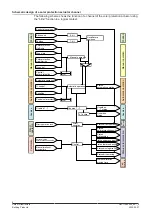
Страница 6: ...Sunshine Central solar protection Override 1 7 Direct operation lock External value solar protection position Start calibration of moving time 8 bit 1 bit Manual operation Delay t Off Automatic operation Delay t Status automatic operation Override 1 7 Direct operation Control Recall store positions 1 active Overrides status Overrides 1 7 status Status direct operation Status upper end position Sta...

Страница 7: ... labeling Example Solar protection actuator N 543D51 8 x 6 A Pos Element Function 1 Connection pins for KNX bus terminal block screwless Connect KNX bus 2 Label field Enter physical address 3 Connection terminals of the relay contacts Connect input and loads 4 Labeling of relay contacts for the drive channels 5 Membrane keypad Execute direct operation Display movement direction and override ...

Страница 8: ...ate direct operation for all channels Pressing the key and pressing the Stop Slat Up Down key 4 6 of a channel Deactivate the direct operation of the respective channel 3 Status LED of direct operation yellow LED flashes if direct operation is active for at least one channel 4 Button Stop slat Up move command of the channel Short press of button 1 s Move command Stop or Lower Activate direct opera...

Страница 9: ...status of the respective channel LED switched off Direct operation is switched off LED lit Move command Up active LED flashing in sync with status LED Direct operation is switched on 5 7 Status LEDs of the channel above and below red Both LEDs lit Override active 8 Test contacts Metering point for voltage testing Type overview Type Description Article number KNX PL Link N 545D31 Solar protection a...

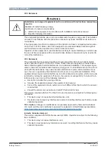
Страница 10: ...N National safety regulations Failure to comply with national safety regulations may result in personal injury and property damage Observe national provisions and comply with the appropriate safety regulations The device should only be installed and put into operation by a certified electrician When connecting the device ensure that the device can be enabled Do not open the casing of the device On...

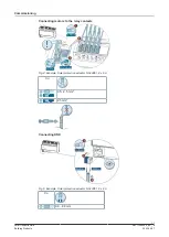
Страница 11: ...uilding Products 2022 04 27 Commissioning Connecting motors to the relay contacts Fig 4 Example Solar protection actuator N 543D51 8 x 6 A Cu 0 5 2 5 mm 2 5 mm Connecting KNX Fig 5 Example Solar protection actuator N 543D51 8 x 6 A Cu 0 6 0 8 mm ...

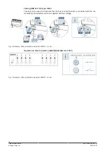
Страница 12: ... can be used to check whether the bus connection cable is connected with the cor rect polarity and whether device is supplied with bus voltage Fig 6 Example Solar protection actuator N 543D51 8 x 6 A Operation in direct operation A B C D E F G H Un 230 V Fig 7 Example Solar protection actuator N 543D51 8 x 6 A ...

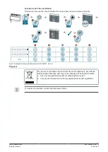
Страница 13: ...Fig 8 Example Solar protection actuator N 543D51 8 x 6 A Disposal The device is considered an electronic device for disposal in accordance with European Directive and may not be disposed of as domestic waste Use only designated channels for disposing the devices Comply with all local and currently applicable laws and regulations If a device is defective contact the local sales office ...

Страница 14: ...termination 75 mA 75 mA Type N 545D31 N 543D51 Service life Mechanical lifespan 50 000 000 switching cycles 50 000 000 switching cycles Electrical lifespan 100 000 switching cycles 100 000 switching cycles Power loss Maximum power loss per device at rated output 2 8 W 5 5 W Maximum power loss per output at rated output 0 66 W 0 66 W Switching capacities load types loads Resistive load 1380 W 1380 ...

Страница 15: ...3 F 158 F Relative humidity non condensing 5 95 Climatic resistance EN 50428 Protection settings Degree of pollution according to IEC 60664 1 2 Overvoltage category according to IEC 60664 1 III Protection class according to EN 60529 IP20 Electrical safety bus yes Electrical safety device complies with EN 50428 EMC requirements device complies with EN 50428 Test mark KNX EAC RCM WEEE China RoHS CE ...

Страница 16: ...ors for control up down or open close e g of solar protection door window or ventilation flaps via channels A B C D G and H The transformers are used to detect the activation of electromagnetic and electronic end po sition switches Fig 9 Example Solar protection actuator N 543D51 8 x 6 A Dimensions Fig 10 Example Solar protection actuator N 543D51 8 x 6 A ...

Страница 17: ...adio frequency energy and if not installed and used in accord ance with the instructions may cause harmful interference to radio communications How ever there is no guarantee that interference will not occur in a particular installation If this equipment does cause harmful interference to radio or television reception which can be de termined by turning the equipment off and on the user is encoura...

Страница 18: ... Global Headquarters Theilerstrasse 1a CH 6300 Zug 41 58 724 2424 www siemens com buildingtechnologies Siemens Switzerland Ltd 2022 Technical specifications and availability subject to change without notice Document ID A6V11986596_en _e Edition 2022 04 27 ...

Отзывы: