Siemens N 512/21 Скачать руководство пользователя страница 4

GAMMA 

instabus


Technical product information 

July 2008 

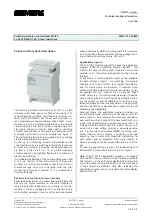
Switching actuator, submodule N 512/21 

5WG1 512-1AB21 

3x AC 230/400V, 16A, C-load, load-check  

Technical manual 

N 512/21, 4 pages 

Siemens AG  


Industry Sector, Building Technologies 

Update: http://www.siemens.com/gamma 

© Siemens AG 2008 

Electrical Installation Technology 


Subject to change without further notice 

P.O. Box 10 09 53, D-93009 Regensburg 

2.4.3.3/4 


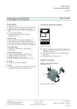
Figure 4. Dismounting the device  


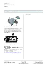
Connecting a switching actuator submodule: see figure 5 

Snap the switching actuator submodule on to the rail 
and push it to the left against the switching actuator 
main module or against the switching actuator sub-
module. Connect both devices using the bridging con-
nector supplied. 


A

B

C


Figure 5. Connecting a switching actuator submodule 


General notes 


Any faulty devices should be returned to the local 
Siemens office. 


If you have further questions about the product,  
please contact our Technical Support: 


+49 (0) 180 50 50-222 

"

  +49 (0) 180 50 50-223 

!


www.siemens.com/automation/support-request


Space for notices 


C3 

C1 

C2 

Содержание N 512/21

Страница 1: ... each submodule output individually which switching state it is to assume on a bus voltage failure and after the bus voltage recov ery as before bus voltage failure ON or OFF Application program The N 512 11 switching actuator needs the application program 07B0 A15 Switching Actuator 981B01 This controls the outputs of the main module as well as the outputs of all connected submodules via their 6 ...

Страница 2: ... data Power supply Bus voltage via the 6 pole bridging connector Bus current per submodule typically 1 mA Power dissipation if all outputs OFF 0 03 W at max load and all outputs ON approx 3 5 W Outputs 3 switching outputs potential free relay contacts rated voltage AC 230 400 V 50 60 Hz rated current 16 AX 200 µF to DIN EN 60669 1 16 A in AC1 mode cos ϕ 0 8 and in AC3 mode cos ϕ 0 45 as to DIN EN ...

Страница 3: ...of protection according to EN 60529 IP 20 Overvoltage category according to IEC 60664 1 III Device complies with EN 50090 2 2 and EN 60669 2 1 EMC requirements Complies with EN 50090 2 2 EN 50428 and EN 60669 2 1 Environmental conditions Climatic withstand capability EN 50090 2 2 Ambient operating temperature 5 45 C Storage temperature 25 70 C Relative humidity not condensing 5 to 93 Markings none...

Страница 4: ... the device Connecting a switching actuator submodule see figure 5 Snap the switching actuator submodule on to the rail and push it to the left against the switching actuator main module or against the switching actuator sub module Connect both devices using the bridging con nector supplied A B C Figure 5 Connecting a switching actuator submodule General notes Any faulty devices should be returned...

Отзывы: