GAMMA
instabus
Technical product information
July 2008
Switching actuator, submodule N 512/21
5WG1 512-1AB21
3x AC 230/400V, 16A, C-load, load-check
Technical manual
N 512/21, 4 pages
Siemens AG
Industry Sector, Building Technologies
Update: http://www.siemens.com/gamma
© Siemens AG 2008
Electrical Installation Technology
Subject to change without further notice
P.O. Box 10 09 53, D-93009 Regensburg
2.4.3.3/2
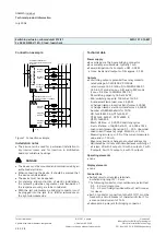
Connection example
Schaltaktor, Hauptmodul
Switching actuator, main module
N 512/11
B
u
sa
n
ko
p
p
le
r
B
u
s
co
u
p
lin
g
u
ni
t
K
N
X
Ausgang 1
Output 1
Ausgang 2
Output 2
Ausgang 3
Output 3
L1
L2
L3
N
L1
L2
L3
2
3
1
A
Schaltaktor, Erweiterung
Switching actuator, submodule
N 512/21
6
Ausgang 1
Output 1
Ausgang 2
Output 2
Ausgang 3
Output 3
L2
L3
2
1
L1
B
C ... E
3
Figure 1. Connection example
Installation notes
•
The device can be used for permanent installation in
dry interior rooms and for insertion in distribution
boards or miniature housings.
V
DANGER
•
The device must be mounted and commissioned by an
authorised electrician.
•
When connecting the device, it should be ensured that
the device can be isolated.
•
The device must not be opened.
•
For planning and construction of electric installations,
the relevant guidelines, regulations and standards of
the respective country are to be considered.
•
With the last submodule no bridging connector must
be plugged into the jack for a further submodule on
the right submodule side.
Technical data
Power supply
•
Bus voltage: via the 6-pole bridging connector
•
Bus current per submodule: typically 1 mA
•
Power dissipation: if all outputs = OFF: 0.03 W,
at max. load and all outputs = ON: approx. 3.5 W
Outputs
•
3 switching outputs, potential-free relay contacts:
- rated voltage: AC 230/400 V, 50/60 Hz
- rated current: 16 AX (200 µF) to DIN EN 60669-1,
16 A in AC1 mode (cos
ϕ
= 0.8) and in AC3 mode
(cos
ϕ
= 0.45) as to DIN EN 60947-4-1,
- DC switching capacity: 16A at 24V DC
- Min. switching capacity: 100 mA at 12V AC
- Incandescent lamp load: max. 3,680 W
- LV halogen lamps, inductive transformer: 2,000 W
- LV halogen lamps, electronic transformer: 2,500 W
- Number of OSRAM ballasts for T5/T8:
QTI 1x28/54W: 56, QTP 1x36W: 31,
QT-M 1x26-42W:21, QTP 2x58W: 9,
QT-FQ 1x80W: 9
- Mech. lifetime: > 1,000,000 switching cycles
- Electr. lifetime: > 100,000 at AC1, > 30,000 at AC3
- Load current measuring range: 0.1...20 A, sinusoidal
- Load current frequency range: 50/60 Hz, +/- 5 Hz,
- Measuring accuracy: +/- 9 % of the current measured
value and +/- 130 mA,
- Max. relay position changes per output and evenly
distributed per minute with simultaneous switching of
all relays: 20 with 3 outputs, 10 with 6 outputs, 7 with
9 outputs, 5 with 12 outputs, 4 with 15 outputs
Operating elements
•
none
Display elements
•
none
Connections
•
Output circuits: screw-type terminals,
insulation strip length 7... 9 mm.
The following conductor cross-sections are permitted:
- 0.5... 4.0 mm² single-core,
- 0.5... 2.5 mm² finely stranded without / with connec-
tor sleeve.
•
Each L-conductor connection to the N 512/11 must be
fused with a circuit-breaker of characteristic B or C for
a max. nominal current of 16 A!
•
Submodule: 6-pole jack for bridging connector.


