GAMMA
instabus
Technical product information
July 2008
Switching actuator, submodule N 512/21
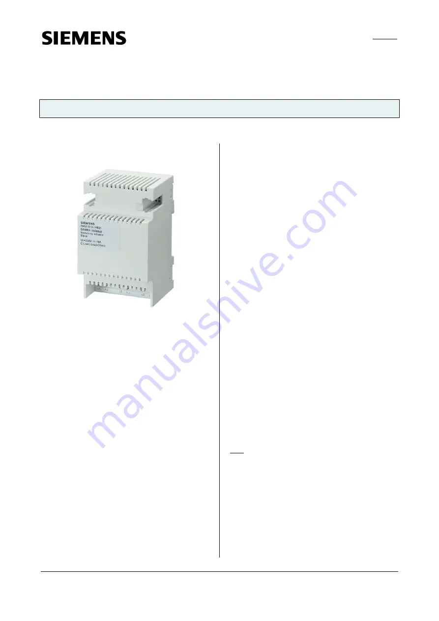
5WG1 512-1AB21
3x AC 230/400V, 16A, C-load, load-check
Siemens AG
N 512/21, 4 pages
Technical manual
Industry Sector, Building Technologies
Electrical Installation Technology
© Siemens AG 2008
Update: http://www.siemens.com/gamma
P.O. Box 10 09 53, D-93009 Regensburg
Subject to change without further notice
2.4.3.3/1
Product and functional description
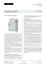
The switching actuator submodule N 512/21 is a 3 MU
(module units) wide device for DIN-rail mounting in N-
system dimensions, with 3 switching outputs (relay con-
tacts) for AC 230/400V, 16A, C-load, each with load cur-
rent measurement and monitoring (load-check). A sub-
module cannot be operated stand-alone or be directly
connected to the bus. But it can be connected via a spe-
cial 6-pole bridging connector either with a switching
actuator main module or with another submodule which
is already connected to a main module (see figure 1).
The submodule electronics are supplied by bus voltage
via the 6-pole bridging connector.
In total up to 4 switching actuator submodules can be
connected in series to a switching actuator main module,
so that a main module, if need be, can be extended sim-
ply from a 3-fold to a 6-, 9-, 12- or 15-fold switching
actuator and thus be matched flexibly to the number of
loads to be switched.
It is indicated by flashing of the corresponding green LED
A to E on the top of the main module if more sub-
modules are set than are actually connected or if the set
submodule type does not correspond with the sub-
module type actually connected or if a submodule is
detected as faulty.
Behavior in case of mains failure / recovery
Because the electronics of a submodule are fed from the
bus (via the 6-pole interface to the main module), a
mains failure then leads solely to a failure of the sub-
module if the bus voltage also fails as the result of a
mains failure. However, it can be set for each submodule
output individually which switching state it is to assume
on a bus voltage failure and after the bus voltage recov-
ery: as before bus voltage failure, ON or OFF.
Application program
The N 512/11 switching actuator needs the application
program "07B0 A15 Switching Actuator 981B01". This
controls the outputs of the main module as well as the
outputs of all connected submodules via their 6-pole
interface.
In bus mode, a communication object can be available
for each actuator output - for switching, for manual
override, for a forced control, for a logical combination
and for status query. Furthermore, if required, time-
limited switching instead of permanent switching on can
be enabled for each channel via an optional "Night
mode" object (e.g. for lighting while cleaning), if need be
with a warning before switching off by multiple switch-
ing the output on and off (flashing). It can also be se-
lected whether all a module's outputs are to be set jointly
and thus identically or whether each output is to be set
separately and individually.
Amongst others, the application program includes op-
tional detection and monitoring of the load current for
each output on load failure and/or overload, simultane-
ous switching of all 3 outputs (3-phase switching), con-
version of a speed given as a percentage value into 1- to
3-stage switching commands (fan speed control), con-
version of a valve setting given as a percentage value
into a pulse width modulated (PWM) switching com-
mand (thermal drive control), a switching cycle and
operating hours count with threshold monitoring for
each output and an integrated 8-bit scene control, in
which each output can be incorporated into up to 8 sce-
nes.
To load the application program, the Engineering Tool
Software (ETS) is required as version 3.0 f or higher.
Note: If the N 512/11 application program is "unloaded"
with the ETS, then you will no longer be able to activate
direct mode, i.e. the LED status display and local switch-
ing of the outputs using the buttons on the front panel
of the actuator are disabled. Only after reloading the
application program can you re-enable the status display
and direct mode.

