Siemens MLC Скачать руководство пользователя страница 4

Siemens Industry, Inc.
Building Technologies  Division

A6V10328217_en--_f

4

3.

The Firmware via USB Port dialog displays a list of available firmware for the
selected module. Select the firmware to be transferred.

4.

Reset the module by depressing the reset switch with a pointed object,
such as a pencil. The power and card fail LEDs should be blinking.

5.

Click on Transfer to begin the module firmware transfer.

If the Transfer button is not pressed within 30 seconds of resetting the MLC, the
module will revert back to operation mode.

6.

After the transfer is completed, click on the 

 button to view the transfer

detail status.

7.

Disconnect the USB cable and reset the module.

Find MLC Software Version

To check for the current version of MLC software in an installed MLC, go to the PMI/
PMI-2/PMI-3 (XLS), FCM2041-U2 (Desigo Fire Safety Modular), FCM2041-U3
(Cerberus PRO Modular) and press the Menu button, select Report, press the More
Info button and select the MLC at that address. Press the Configuration soft key,
press Appl Rev for the Application Version and press View.

WIRING

All field wiring to the MLC is connected to the terminal blocks of the CC-5/CC-2 card
cage slot in which it is installed.

To Connect External Wiring

1.

Loosen the screw of the terminal by turning it counterclockwise.

2.

Insert the wire into the side of the terminal block.

3.

Tighten the screw of the terminal block by turning it clockwise.
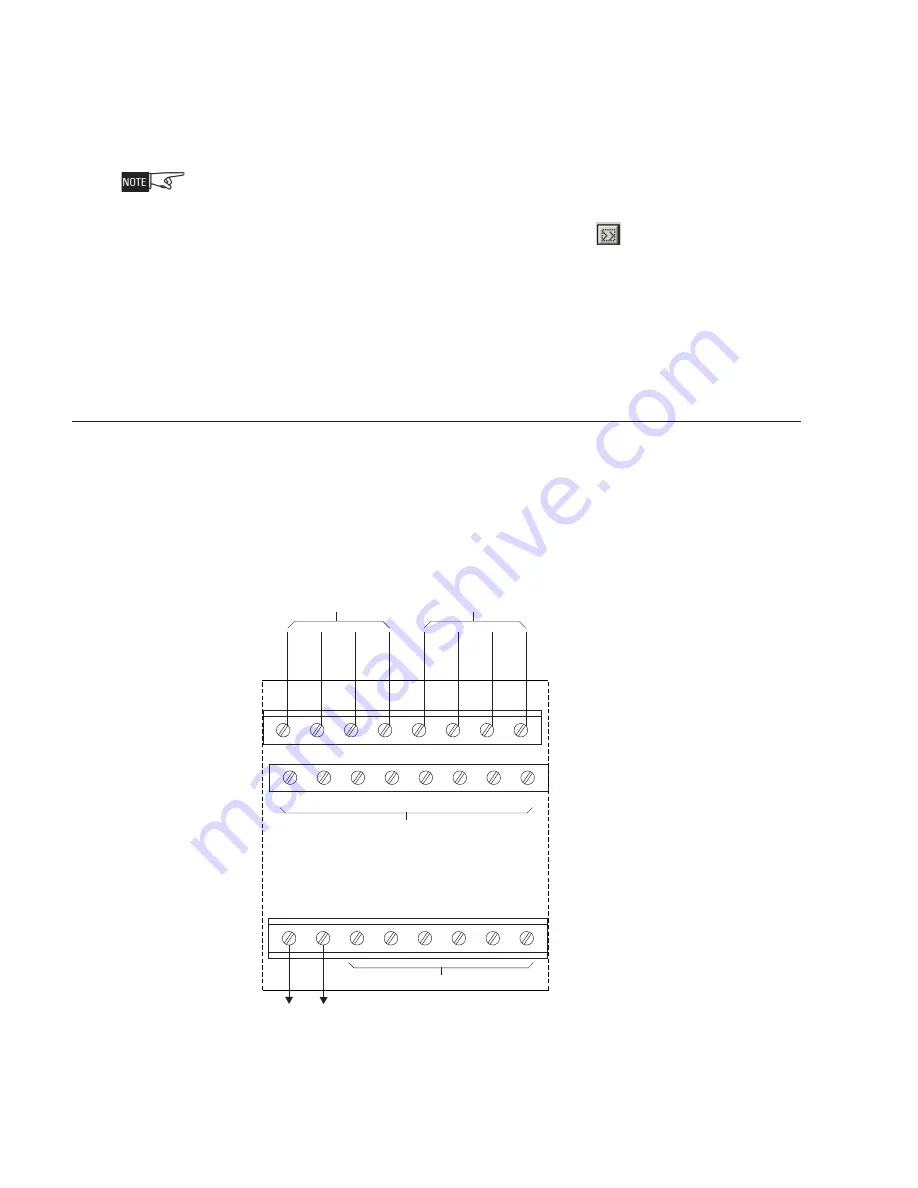
Figure 3

Wiring The 24VDC Power Lines To The MLC Slot In The CC-5/CC-2

1

2

3

4

5

6

7

8

9

10

11

12

13

14

15

16

17

18

19

20

21

22

23

24

24V+

LOOP 1

LOOP 2

24V-

TO 24VDC FROM THE PSC-12

ONE SLOT OF CC-5/CC-2

DO NOT USE

DO NOT USE

Содержание MLC

Страница 1: ...ates and maintains all devices residing on the loop The MLC communicates all relevant device and event information such as alarms and troubles to the PMI PMI 2 PMI 3 XLS FCM2041 U2 Desigo Fire Safety Modular FCM2041 U3 Cerberus PRO Modular The sensitivity of any intelligent smoke detector and the logic functions of any intelligent output devices can be checked and adjusted from the PMI PMI 2 PMI 3...

Страница 2: ...IL Yellow Normally OFF When illuminated indicates hardware failure on the card or unsuccessful firmware upload During firmware upload this LED should blink HNET FAIL Yellow Normally OFF When illuminated indicates that the HNET communica tion with the MLC has terminated ALARM Red Normally OFF When illuminated indicates that the MLC has detected an alarm TROUBLE Yellow Normally OFF When illuminated ...

Страница 3: ...d cage Refer to Figure 2 Insert the MLC card into the card guides rightside up lettering on the front panel is legible Slide the card in until the card edge connectors contact the receptacles on the motherboard Verify that the DIN connectors of the card and the card cage aligned properly The card can only plug in one direction to the card cage if it does not align DO NOT FORCE the card Place thumb...

Страница 4: ...rrent version of MLC software in an installed MLC go to the PMI PMI 2 PMI 3 XLS FCM2041 U2 Desigo Fire Safety Modular FCM2041 U3 Cerberus PRO Modular and press the Menu button select Report press the More Info button and select the MLC at that address Press the Configuration soft key press Appl Rev for the Application Version and press View WIRING All field wiring to the MLC is connected to the te...

Страница 5: ... DCLA LOOP 1 INITIATING DEVICE CC 5 CC 2 LOOP 2 OPERATES IN FULL CONFORMANCE WITH STYLE 4 ULC DCLB INITIATING DEVICE Connect 24V from the PSC 12 PSX 12 to terminal 17 and 24V from the PSC 12 PSX 12 to terminal 18 of the slot in the CC 5 CC 2 where the MLC will be installed Refer to Figure 3 Each device loop circuit can be wired Class B or Class A MLC field circuit wiring does not require twisted s...

Страница 6: ...N P 0 3 1 1 P F T P D A B D h t i w S R 3 X B D S 3 B D r o 1 1 X B D A S R 1 1 X B D 1 1 B D 1 2 9 5 9 0 5 1 3 N P 1 2 9 5 9 0 5 1 3 N P 0 6 1 1 T P F T P D A B D h t i w S R 3 X B D S 3 B D r o 1 1 X B D A S R 1 1 X B D 1 1 B D 1 2 9 5 9 0 5 1 3 N P 1 2 9 5 9 0 5 1 3 N P 0 6 P C I 1 7 4 2 9 0 5 1 3 N P 2 1 6 B P C I 6 0 3 5 9 0 5 1 3 N P 2 1 H 1 1 I L I S R 3 X B D S 3 B D 7 8 3 5 9 0 5 1 3 N P ...

Страница 7: ...o n n a c e g a s u y t i r u c e s h t i w s e c i v e d I R T 8 4 6 8 L U o t d e t s i l y l s u o i v e r p s e c i v e d h t n o i t i d E CZM 1 1B6 Compatibility Table 3 contains compatibility data for the CZM 1 1B6 when the CZM 1 1B6 is configured to perform alarm verification Each detector model is listed with the allowable Zeus alarm verification delay range in seconds This setting is mad...

Страница 8: ...ion feature but can be used when alarm verification is disabled Each detector is assigned a category Do not mix detectors from different categories on the same circuit ELECTRICAL RATINGS t n e r r u C e n a l P k c a B V 4 2 A m 8 2 t n e r r u C V 4 2 l a n i m r e T w e r c S e c i v e d r e p A m 5 1 A m 0 9 t n e r r u C e n a l P k c a B 2 6 A m 5 1 t n e r r u C y b d n a t S V 4 2 e c i v e...

Страница 9: ...ce and this paragraph are duplicated in all such forms and that any documentation advertising materials and other materials related to such distribution and use acknowledge that the software was developed by Carnegie Mellon University The name of the University may not be used to endorse or promote products derived from this software without specific prior written permission THIS SOFTWARE IS PROVI...

Страница 10: ...Siemens Industry Inc Building Technologies Division Florham Park NJ Siemens Canada Ltd 1577 North Service Road East Oakville Ontario L6H 0H6 Canada Document ID A6V10328217_en _f P N A5Q00066395 ...

Отзывы: