Siemens MLC Скачать руководство пользователя страница 3

Siemens Industry, Inc.
Building Technologies  Division

A6V10328217_en--_f

3

PRE-INSTALLATION

The following components must be set prior to inserting the card into the CC-5/CC-2
(refer to Figure 2):

The MLC uses two module addresses in the HNET network. Set the lower of the
two consecutive three-digit HNET network addresses (odd or even) for the MLC
using the three rotary dial switches located near the bottom of the front panel. (Refer
to Figure 1 for the location of the switches.)  The address for the MLC must be the
same as the address selected for it in the Zeus Programming Tool. To set the address,
turn the pointers on each of the three dials to the numbers for the selected address.
For example, if the address is 123, set the pointer for the HUNDREDS dial to “1”, set
the pointer for the TENS dial to “2”, and set the pointer for the ONES dial to “3”.  The
range of allowable addresses is from 001 to 251 (leading zeros must be used).

INSTALLATION

Remove all system power before installation, first battery then AC. (To power up,

connect the AC first, then the battery.)

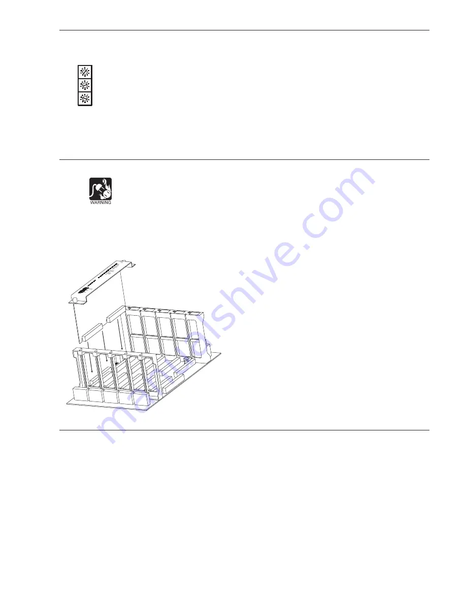
The MLC plugs perpendicularly into one slot in the CC-5/CC-2 card-cage via two 96-
pin DIN connectors and can occupy any slot in the card cage. (Refer to Figure 2.)

Insert the MLC card into the card guides rightside up (lettering on the front panel is
legible).

Slide the card in until the card edge connectors contact the
receptacles on the motherboard.

Verify that the DIN connectors of the card and the card-cage
aligned properly. The card can only plug in one direction to the
card cage, if it does not align, DO NOT FORCE the card.

Place thumbs on the front panel adjacent to the captive
screws and gently apply even pressure on the card until the
connectors seat in the receptacles on the motherboard.

Secure with the captive screws.

FIRMWARE UPGRADES

The MLC is shipped with the latest firmware and the user should not have to
upgrade unless suggested to do so by Siemens Industry, Inc. Technical Support.
From time to time, modules used in XLS/Desigo Fire Safety Modular/Cerberus PRO
Modular systems are upgraded to improve their operation or to add to their capabili-
ties with new features. Firmware in the MLC is field upgradable. Refer to the Zeus
Quickstart Manual, P/N 315-033875, and Zeus Help for additional details.

1.

Plug one end of a user-supplied USB A to B cable into the USB port on the
front of the MLC. Plug the other end into the host PC.

2.

In Zeus, select the module to be upgraded in the Physical Tree. Then select
the 

Build>Transfer>Module Firmware to Panel

 menu.

HNET

HUNDREDS

TENS

ONES

Figure 2

Installing The  MLC

Содержание MLC

Страница 1: ...ates and maintains all devices residing on the loop The MLC communicates all relevant device and event information such as alarms and troubles to the PMI PMI 2 PMI 3 XLS FCM2041 U2 Desigo Fire Safety Modular FCM2041 U3 Cerberus PRO Modular The sensitivity of any intelligent smoke detector and the logic functions of any intelligent output devices can be checked and adjusted from the PMI PMI 2 PMI 3...

Страница 2: ...IL Yellow Normally OFF When illuminated indicates hardware failure on the card or unsuccessful firmware upload During firmware upload this LED should blink HNET FAIL Yellow Normally OFF When illuminated indicates that the HNET communica tion with the MLC has terminated ALARM Red Normally OFF When illuminated indicates that the MLC has detected an alarm TROUBLE Yellow Normally OFF When illuminated ...

Страница 3: ...d cage Refer to Figure 2 Insert the MLC card into the card guides rightside up lettering on the front panel is legible Slide the card in until the card edge connectors contact the receptacles on the motherboard Verify that the DIN connectors of the card and the card cage aligned properly The card can only plug in one direction to the card cage if it does not align DO NOT FORCE the card Place thumb...

Страница 4: ...rrent version of MLC software in an installed MLC go to the PMI PMI 2 PMI 3 XLS FCM2041 U2 Desigo Fire Safety Modular FCM2041 U3 Cerberus PRO Modular and press the Menu button select Report press the More Info button and select the MLC at that address Press the Configuration soft key press Appl Rev for the Application Version and press View WIRING All field wiring to the MLC is connected to the te...

Страница 5: ... DCLA LOOP 1 INITIATING DEVICE CC 5 CC 2 LOOP 2 OPERATES IN FULL CONFORMANCE WITH STYLE 4 ULC DCLB INITIATING DEVICE Connect 24V from the PSC 12 PSX 12 to terminal 17 and 24V from the PSC 12 PSX 12 to terminal 18 of the slot in the CC 5 CC 2 where the MLC will be installed Refer to Figure 3 Each device loop circuit can be wired Class B or Class A MLC field circuit wiring does not require twisted s...

Страница 6: ...N P 0 3 1 1 P F T P D A B D h t i w S R 3 X B D S 3 B D r o 1 1 X B D A S R 1 1 X B D 1 1 B D 1 2 9 5 9 0 5 1 3 N P 1 2 9 5 9 0 5 1 3 N P 0 6 1 1 T P F T P D A B D h t i w S R 3 X B D S 3 B D r o 1 1 X B D A S R 1 1 X B D 1 1 B D 1 2 9 5 9 0 5 1 3 N P 1 2 9 5 9 0 5 1 3 N P 0 6 P C I 1 7 4 2 9 0 5 1 3 N P 2 1 6 B P C I 6 0 3 5 9 0 5 1 3 N P 2 1 H 1 1 I L I S R 3 X B D S 3 B D 7 8 3 5 9 0 5 1 3 N P ...

Страница 7: ...o n n a c e g a s u y t i r u c e s h t i w s e c i v e d I R T 8 4 6 8 L U o t d e t s i l y l s u o i v e r p s e c i v e d h t n o i t i d E CZM 1 1B6 Compatibility Table 3 contains compatibility data for the CZM 1 1B6 when the CZM 1 1B6 is configured to perform alarm verification Each detector model is listed with the allowable Zeus alarm verification delay range in seconds This setting is mad...

Страница 8: ...ion feature but can be used when alarm verification is disabled Each detector is assigned a category Do not mix detectors from different categories on the same circuit ELECTRICAL RATINGS t n e r r u C e n a l P k c a B V 4 2 A m 8 2 t n e r r u C V 4 2 l a n i m r e T w e r c S e c i v e d r e p A m 5 1 A m 0 9 t n e r r u C e n a l P k c a B 2 6 A m 5 1 t n e r r u C y b d n a t S V 4 2 e c i v e...

Страница 9: ...ce and this paragraph are duplicated in all such forms and that any documentation advertising materials and other materials related to such distribution and use acknowledge that the software was developed by Carnegie Mellon University The name of the University may not be used to endorse or promote products derived from this software without specific prior written permission THIS SOFTWARE IS PROVI...

Страница 10: ...Siemens Industry Inc Building Technologies Division Florham Park NJ Siemens Canada Ltd 1577 North Service Road East Oakville Ontario L6H 0H6 Canada Document ID A6V10328217_en _f P N A5Q00066395 ...

Отзывы: