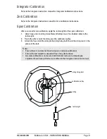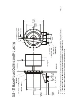
ILE - 37 B
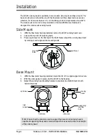
ase Mount Outline and Mount
ing
No
te
s:
1.
Re
fer to Flowmet
er dr
awing for
the
dimension
from
the s
ensing h
ead mount
ing
hole
to the
fl
ow
guide c
ent
erline.
2.
The sens
ing head
suppor
t plat
e should be
rigid and inde
pe
ndent of the Flowmet
er
housing.
3.
Ens
ur
e that t
he out
er
gasket s
eal t
o t
he Flowmet
er h
ousing wall is dust
tigh
t.
out
er gasket
co
nd
ui
t entr
y 1/2" NPT (i
nt
er
na
l)
fiber
glass c
ov
er
280 mm
(1
1")
25
6 mm
(10.06")
50
mm
(1
.97")
90 m
m
(3
.54")
70 mm (2.76
")
290
mm (
11
.5
")
30 mm
(1
.18
")
sensing plat
e
see
Not
e
1.
8 mm (0.31")
di
a., 1
8
bo
lts
on
360 mm
(1
4.1
7") B
.D
.C.
as r
eq
ui
red
385 mm (1
5.1
2"
)
260
mm
(10.25")
180 mm (7
.0
9"
)
su
ppo
rt
pl
at
e
(c
usto
mer
-sup
pl
ied
)
10
mm (
0.38")
di
a.
(4
le
ve
lling
ro
ds
)
FIG
. 2
Содержание milltronics ILE-37
Страница 1: ...Instruction Manual September 2003 ILE 37 milltronics ...
Страница 4: ...ii ...
Страница 25: ...Notes ...
Страница 26: ...Notes ...
Страница 27: ......

