


5/39
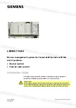
Smart Infrastructure
LMV6 Installation Guide
CC1J7560en
1
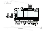
Installation
notes
4/21/2020
1 Installation
notes
Always run the high-voltage ignition cables separately from the LMV6 and other
cables while observing the greatest possible distances
Do not mix up phase and neutral (midpoint) conductors
Install switches, fuses, and grounding in accordance with local regulations
The connection diagrams show the LMV6 with earthed neutral conductor. It is
essential to ensure that local regulations are complied with (e.g., protection against
electric shock)
Do not exceed the maximum permissible current rating of the connection terminals
Ensure that the electrical wiring inside the burner complies with national and local
regulations
Do not feed external mains voltage to the control outputs of the LMV6. When
checking the functions of the burner components controlled by the LMV6 (fuel
valves or similar), the LMV6 must not be connected to the burner components
Mains power may only be supplied via
L
and
N
. There must be no difference in
potential between the neutral conductor
N
and protective earth
PE
Circuit breakers should have a characteristic “C” when operated with the LMV6
Make certain that strain relief of the connected cables is in compliance with the
relevant standards (e.g., as per DIN EN 60730 and DIN EN 60335)
Ensure that spliced wires cannot come into contact with neighboring connections.
Use suitable ferrules. Failure to observe this information poses a risk of loss of
safety functions and a risk of electric shock
Unused connections on the LMV6 must be fitted with a corresponding AGG9
connector by the burner manufacturer
The AGG9 connectors on the connection cables for the LMV6 may only be removed
or replaced when the plant is shut down (all-pole disconnection)
The connection between the SQM4 and the controlling elements for fuel and
combustion air, as well as any additional controlling elements, must be form-fitted
The AZL66 must be used in a dry and clean environment
Check the connection cables for the supervision switch inputs (e.g., the air pressure
switch) for signs of a short circuit