15/39
Smart Infrastructure
LMV6 Installation Guide
CC1J7560en
3 Description of the terminals
4/21/2020
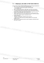
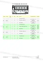
3.1.6 Terminal X91 / X92 / X93
X91
X92
X93
1 2 3 4 1
LINE
X
9
1 X
92 X
93
/0
11
9
Figure 9: Description of terminal X91 / X92 / X93
Terminal Coding
Type
(ASN)
Pin
Input
Output
Function
Electrical limit value
Parameter
X91 *)
04K77
1
---
---
Protective earth (PE)
---
---
2
---
---
Neutral conductor (N)
---
3
---
---
Auxiliary terminal
---
4
---
●
Fuel valve V1
230 V~ +10% / -15%
50 Hz
2 A, cos
φ
0.4
X92
03K15
1
---
●
---
---
---
2
---
●
Alarm
---
3
●
---
Reset
---
X93
05K30
1
●
---
Safety loop
230 V~ +10% / -15%
50 Hz
max. 5 A
0925
2
---
●
Power supply safety loop
---
3
---
---
Protective earth (PE)
---
4
---
---
Neutral
---
5
●
---
Mains power supply
5 A
*)
Note!
Valve proving via fuel valve circuit!
With activated valve proving via fuel valve circuit
Rated current
1 A
Load
factor Cos
0.4
Note!
Terminal X93 pin 1 or pin 2 and components of the safety loop!
The total current of all components connected to the LMV6 flows via terminal X93
pin 1 or pin 2 and components of the safety loop.
Caution!
Contacts in the safety loop!
In the safety loop, temporarily switching (< 1 second) contacts, buttons or
similar must not be wired.

