22/61
Building Technologies
Basic Documentation LMO39…
CC1P7154en
6 Technical data
15.03.2018
6.4 Flame supervision with QRB... or QRC...
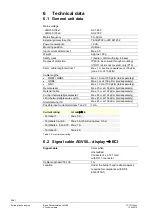
Detector current
required
(with flame)
Perm. detector
current
(without flame)
Possible detector current
with flame
(typically)
QRB1
¹)
Min. 45 µA
Max. 5,5 µA
100 µA
QRB3
¹)
Min. 45 µA
Max. 5,5 µA
100 µA
QRB4
¹)
Min. 45 µA
Max. 5,5 µA
70 µA
QRC
¹)
Min. 45 µA
Max. 5,5 µA
70 µA
Table 3: Detector data QRB…/QRC…
¹) The values given in the table above only apply under the following conditions:
- Mains voltage depending on execution AC 120 V or AC 230 V
- Ambient temperature 23 °C
Detector current in operation:
- Flame signal instable
-
Green signal lamp (LED) flashing
Detector current in operation:
- Flame signal stable
-
Green signal lamp (LED) steady on
QRB... ¹)
<45 µA
>45 µA
QRC... ¹)
<45 µA
>45 µA
Table 4: Detector data signal lamp LED
¹) The values given in the table above only apply under the following conditions:
- Mains voltage depending on execution AC 120 V or AC 230 V
- Ambient temperature 23 °C
QRB...
QRC...
12
11
LMO...
bl
µA DC
+
QRB...
7130v01/0700
sw
12
11
LMO...
1
sw
bl
br
µA DC
+
QRC1...
7130v02/0700
Legend
µA DC DC microammeter
with an internal
resistance of
Ri = max. 5 k
ς
bl
Blue
sw
Black
br
Brown
Figure 6: Measuring circuit for detector current
Alternatively, interface OCI400/OCI410 with PC software ACS410 or AZL2 (parameter
954) can be used to measure the detector current.
In that case, the DC microammeter is not required.
Β
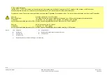
Note!
QRB4 cable connection!
Connect the blue QRB4 cable to terminal 11.
Connect the black QRB4 cable to terminal 12.
Otherwise the QRB4 will not function.
Green signal lamp (LED) for
indication of operating state
Measuring circuit
for detector current


