


Landis & Staefa Division
CC1N7421E
December 04, 1998
3/16
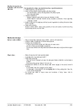
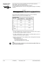
It is important to achieve practically loss-free signal transmission
•
Cable length may not exceed 20 m
•
Never run the detector cable together with other cables
–
Line capacitances reduce the magnitude of the flame signal
–
Use a separate cable
•
Insulation resistance
–
Between detector electrode and ground: minimum 50 M
Ω
–
Soiled detector electrode holders reduce insulation resistance, thus supporting
creepage currents
•
Earth the burner in compliance with the relevant regulations; earthing the boiler alone
does not suffice
•
Observe the polarity
Burner controls LMG2... detect wrong polarity of live and neutral, in which case they
initiate lockout at the end of «TSA»
–
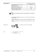
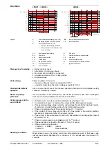
Plug-in design like predecessor type LGB2... (refer to «Dimensions»)
–
Housing made of impact-proof, heat-resistant plastic
–
Housing accommodates the
- control of the microcontroller with PCB relay for load control
- electronic flame signal amplifier (ionization)
- lockout reset button with integrated red fault indication lamp and green flame signal
lamp
–
Made of impact-proof, heat-resistant plastic
–
Available with screw terminals AGK11
–
Cable entry optionally
- from the front or laterally by means of cable gland holders AGK65 or cable holders
AGK66
- from below through two holes of 16.2 mm dia.
–
Provided with catches on the two narrow sides which engage in the burner control's
housing
- must audibly click when plugging in the LMG2...
- to disengage, a screwdriver must be slightly tilted in the guiding slots; then, the
burner control slightly lifts
–
For length and width of plug-in base and positions of fixing holes, refer to
«Dimensions»
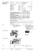
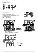
Electrical connection of
ionization current and UV
detectors
Mechanical design
Burner controls LMG2...
Plug-in base