


Technical reference
A.10 Flow calculation
HydroRanger 200 HMI
308
Operating Instructions, 06/2018, A5E36281317-AC
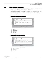
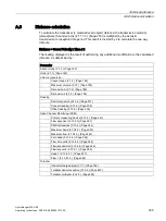
Vessel shape
1)
set to Universal Curved
This calculation creates a cubic spline approximation of the level/volume curve, providing
best results if the curve is non-linear and there are no sharp angles.
Select at least enough breakpoints from the curve to satisfy the following:
●
two breakpoints very near the minimum level
●
one breakpoint at the tangent points of each arc
●
one breakpoint at each arc apex
●
two breakpoints very near the maximum level
For combination curves, enter at least two breakpoints immediately before and after any
sharp angle (as well as one breakpoint exactly at the angle) on the curve.
1)
Vessel shape (2.7.2.) (Page 186)
A.10
Flow calculation
The device provides numerous OCM flow calculation features:
●
Primary measuring device (2.13.2.) (Page 240)
●
PMD dimensions (2.13.5.) (Page 246)
●
Flow exponent (2.13.4.1) (Page 241)
●
Maximum head (2.13.4.2.) (Page 243)
●
Maximum flow (2.13.4.3.) (Page 243)
●
Flow time units (2.13.4.4.) (Page 244)
●
Zero head (2.13.4.5.) (Page 244)
●
Flowrate decimal (2.13.4.6.) (Page 245)
●
Flowrate units (2.13.4.7.) (Page 245)
●
Head 1 (2.13.6.1.1.) (Page 247)
●
Flow 1 (2.13.6.1.2.) (Page 248)
If the PMD (primary measuring device) does not match any of the eight preset PMD
calculations, or if a PMD is not used, select a Universal Volume calculation. Use the head/
flow graph or chart provided by the PMD fabricator (or create one based on the PMD or
channel dimensions).
Содержание HydroRanger 200 HMI
Страница 2: ......
Страница 20: ...Introduction 1 5 Notes on warranty HydroRanger 200 HMI 18 Operating Instructions 06 2018 A5E36281317 AC ...
Страница 24: ...Safety notes HydroRanger 200 HMI 22 Operating Instructions 06 2018 A5E36281317 AC ...
Страница 28: ...Description 3 5 Modbus communication HydroRanger 200 HMI 26 Operating Instructions 06 2018 A5E36281317 AC ...
Страница 159: ...Parameter reference 8 2 Parameter indexing HydroRanger 200 HMI Operating Instructions 06 2018 A5E36281317 AC 157 ...
Страница 276: ...Parameter reference 8 10 Language 6 HydroRanger 200 HMI 274 Operating Instructions 06 2018 A5E36281317 AC ...
Страница 322: ...Pump control reference B 13 Other pump controls HydroRanger 200 HMI 320 Operating Instructions 06 2018 A5E36281317 AC ...
Страница 352: ...Communications C 41 Single parameter access SPA HydroRanger 200 HMI 350 Operating Instructions 06 2018 A5E36281317 AC ...
Страница 354: ...Updating software HydroRanger 200 HMI 352 Operating Instructions 06 2018 A5E36281317 AC ...
Страница 359: ...HydroRanger 200 HMI Operating Instructions 06 2018 A5E36281317 AC 357 Conduit entry for Class I Div 2 applications F ...
Страница 360: ...Conduit entry for Class I Div 2 applications HydroRanger 200 HMI 358 Operating Instructions 06 2018 A5E36281317 AC ...
Страница 361: ...Conduit entry for Class I Div 2 applications HydroRanger 200 HMI Operating Instructions 06 2018 A5E36281317 AC 359 ...
Страница 362: ......
Страница 372: ...Programming chart G 1 Programming chart HydroRanger 200 HMI 370 Operating Instructions 06 2018 A5E36281317 AC ...
Страница 390: ...LCD menu structure H 1 LCD Menu Structure HydroRanger 200 HMI 388 Operating Instructions 06 2018 A5E36281317 AC ...
Страница 403: ......