


10/12
2019-03-25
A6V11476940_----_a
A5W00052150 A
Siemens Building Technologies
de
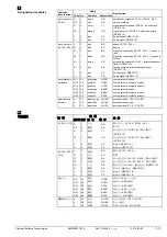
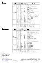
Kabelbezeichnungen
Anschluss
Kabel
Bedeutung
Code Nr.
Farbe
Akürzung
Antriebe
G
1
rot
RD
System Potential AC 24 V ~/DC 24…48 V
⎓
AC 24 V
G0
2
schwarz
BK
Systemnull
Y1
6
violett
VT
Stellsignal AC/DC 0 V "Uhrzeigersinn"
(GEB14..1E)
Y2
7
orange
OG
Stellsignal AC/DC 0 V "Gegenuhrzeigersinn"
(GEB14..1E)
Y
8
grau
GY
Signaleingang (GEB16..1E)
U
9
rosa
PK
Signalausgang (GEB16..1E)
Antriebe
L
3
braun
BR
Phase AC 100…240 V ~
AC 100…240 V N
4
blau
BU
Nullleiter
Y1
6
schwarz
BK
Stellsignal AC 100…240 V ~ “Uhrzeigersinn”
(GEB34..1E)
Y2
7
weiss
WH
Stellsignal AC 100…240 V ~ “Gegenuhrzeiger-
sinn” (GEB34..1E)
G+
1
rot
RD
System Potential DC 24 V ~ (Hilfsspeisung)
(GEB361.1E)
G-
2
schwarz
BK
Systemnull (Hilfsspeisung) (GEB361.1E)
Y
8
grau
GY
Signaleingang (GEB361.1E)
U
9
rosa
PK
Signalausgang (GEB361.1E)
Hilfsschalter
Q11
S1
grau/rot
GYRD
Schalter A Eingang
Q12
S2
grau/blau
GYBU
Schalter A Ruhekontakt
Q14
S3
grau/rosa
GYPK
Schalter A Schliesskontakt
Q21
S4
schwarz/rot
BKRD
Schalter B Eingang
Q22
S5
schwarz/blau BKBU
Schalter B Ruhekontakt
Q24
S6
schwarz/rosa BKPK
Schalter B Schliesskontakt
Rückführ-
a
P1
weiss/rot
WHRD
Potentiometer 0...100 % (P1-P2)
potentimeter
b
P2
weiss/blau
WHBU
Potentiometer Abgriff
c
P3
weiss/rosa
WHPK
Potentiometer 100...0 % (P3-P2)
en
Wire designations
Connection
Cable
Meaning
Code No.
Color
Abbreviation
AC 24 V
G
1
red
RD
System potential AC 24 V ~/DC 24…48 V
⎓
Actuators
G0
2
black
BK
System neutral
Y1
6
purple
VT
Actuating signal AC/DC 0 V "clockwise"
(GEB14..1E)
Y2
7
orange
OG
Actuating signal AC/DC 0 V "anticlockwise"
(GEB14..1E)
Y
8
gray
GY
Signal in (GEB16..1E)
U
9
pink
PK
Signal out (GEB16..1E)
AC 100…240 V L
3
brown
BR
Line AC 100…240 V ~
Actuators
N
4
blue
BU
Neutral
Y1
6
black
BK
Actuating signal AC 100…240 V ~, "clockwise"
(GEB34..1E)
Y2
7
white
WH
Actuating signal AC 100…240 V ~, "anticlock-
wise" (GEB34..1E)
G+
1
red
RD
System potential DC 24 V ~ (aux. power supply)
(GEB361.1E)
G-
2
black
BK
System neutral (aux. power supply) (GEB361.1E)
Y
8
gray
GY
Signal in (GEB361.1E)
U
9
pink
PK
Signal out (GEB361.1E)
Auxiliary switch Q11
S1
gray/red
GYRD
Switch A input
Q12
S2
gray/blue
GYBU
Switch A normally closed contact
Q14
S3
gray/pink
GYPK
Switch A normally open contact
Q21
S4
black/red
BKRD
Switch B input
Q22
S5
black/blue
BKBU
Switch B normally closed contact
Q24
S6
black/pink
BKPK
Switch B normally open contact
Feedback
a
P1
white/red
WHRD
Potentiometer 0...100 % (P1-P2)
potentiometer
b
P2
white/blue
WHBU
Potentiometer pick-off
c
P3
white/pink
WHPK
Potentiometer 100...0 % (P3-P2)