
2
A6V10349619_h_--_--
en
Installation
WARNING
Electrostatic charge when mounting and
installing equipment in potentially explosive
atmospheres
Risk of explosion
1.
You must only mount and install the devices if the
atmosphere in the area is not potentially
explosive.
2.
You must ensure compliance with applicable
regulations and recommendations for the
mounting and installation of devices in potentially
explosive areas.
3.
Avoid electrostatic charging of devices during
cleaning and maintenance work.
Prior to installing the manual call points, read and follow
the instructions in document A6V10324618.
Description
The manual call point FDM223-Ex is used to activate alarms
manually in the event of a fire.
The manual call point is suitable for installation in potentially
explosive areas.
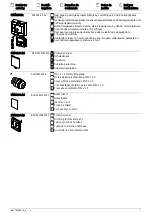
A protective cover and metal cable glands are available to
purchase as accessories (see Fig. 4).
Intended use
The manual call point FDM223-Ex must only be used as
follows:
·
On an FDnet-Ex-/C-NET-Ex detector line in the
FS20/FS720 fire detection installation
·
On the detector line, the manual call point must be
installed downstream of a line adapter (Ex) approved in
accordance with national and international regulations.
For the FDnet-/C-NET detector line, this is line adapter
(Ex) FDCL221-Ex.
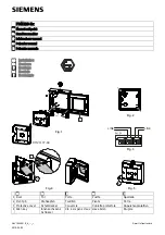
Preparation
1.
Use the Allen key (4) supplied to open the door (1) of the
housing (see Fig. 5). Keep the Allen key (4) in a safe place.
2.
Determine the feed opening in the housing and break it out
from above or below.
Installation
1.
Secure the housing at a height of 0.9…1.6 m on an even
surface.
Observe the country-specific regulations for the
exact installation height!
-
Only use the screw holes marked by arrows (see Fig. 2).
2.
Pull the cable through the supplied cable grippers. If
necessary: Use metal cable glands (accessories).
3.
Pull the cable into the housing through the feed opening.
4.
Close unused housing openings with cable grippers.
5.
Use the Allen key (4) to close the door (1).
Installing the protective cover DMZ1197-AC
1.
Remove the glass insert.
2.
Guide the protective cover through the opening in the
door (1) from the front.
3.
Insert the pivot pins (2) for the protective cover into the two
recesses provided on the rear side of the door (1) (see
Fig. 4).
4.
Install the glass insert.
Connecting the switching unit to the electricity
1.
Use the Allen key (4) to open the door (1) of the housing.
2.
If the detector line cables (LINE) are shielded, connect the
shielding with an auxiliary terminal. When the external
alarm indicator (Ext. Al) is connected via a shielded cable,
the shielding must be connected to the positive pole of the
alarm indicator by means of an auxiliary terminal.
The shielding must not touch any other potentials or metal
parts in the manual call point.
3.
Connect the feed line to the terminals in the switching unit
(see Fig. 3) in accordance with the connection diagram.
Note the positive and negative poles.
Only connect one wire per terminal. This is the
only way to ensure the connection is failure-free
for the entire service life of the device.
4.
When inserting the switching unit into the housing, note the
feed line. Avoid crushing the feed line.
5.
Insert the switching unit in the housing with the terminals
facing upwards and secure it using two screws.
WARNING
Deactivating the manual call points prevents
alarms from being forwarded
Alarming does not take place
Mark deactivated or non-functional manual call
points with "NOT IN USE"!
6.
Use the Allen key (4) to close the door (1).
You will find more information in
documents A6V10349616 and A6V10324618.


