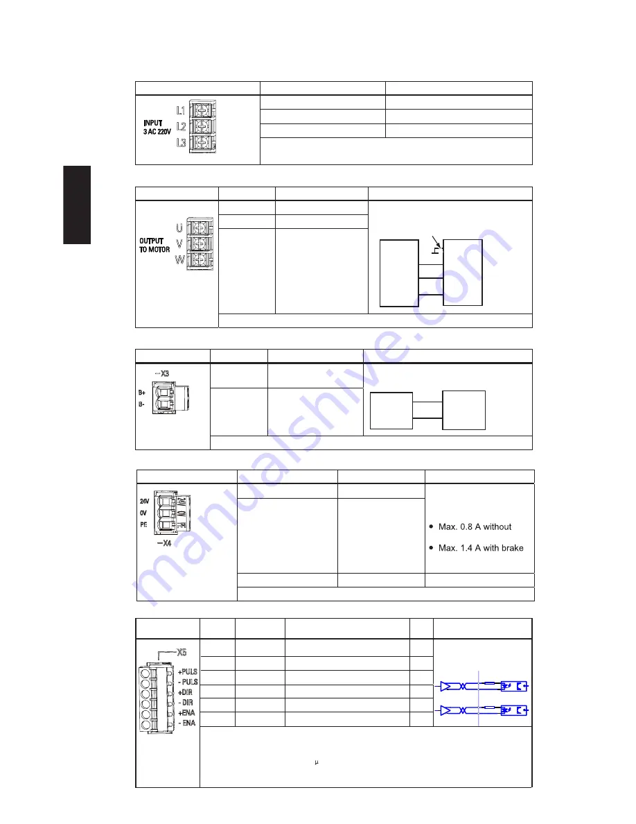
2.3 Interface Definition
Line supply connection L1, L2, L3
Motor output connection U, V, W
Motor brake connection X3
DC 24 V power supply connection X4
EN-16
SINAMICS V60 Controlled Power Module (CPM60.1) Getting Started
Installation
Setpoint interface X5
Pulse input se
+PULS
-PULS
+DIR
+ENA
-ENA
-DIR
Direction of motor se
Pulse
Pulse enable -
Direction of motor setpoint -
Pulse input setpoint -
1
2
3
4
5
6
I
I
I
I
I
I
Interface
Signal name
Description
Interface
Signal name
Schematic connection diagram
Description
Interface
Signal name
Schematic connection diagram
Description
Interface
Interface
Pin
Signal name
Signal
name
I/O
type
Remark
Remark
Description
Description
Voltage 24 V DC
(20.4 - 28.8 V)
Current consumption:
brake power supply
power supply
Maximum conductor cross-section: 1.5 mm
2
Maximum conductor cross-section: 1.5 mm
2
Maximum conductor cross-section: 2.5 mm
2
Maximum conductor cross-section: 2.5 mm
2
+ 24 V, motor brake
voltage positive
B+
B-
0 V, motor brake
voltage negative
B+
White
Black
Drive side
(Terminal strip)
Motor side
(Socket connector)
B-
1
2
B-
B+
2
1
U
Drive side
(Terminal strip)
Motor side
(Socket connector)
V
W
1
Black
Yellow-Green
Black
Black
2
3
U
PE
V
W
2
1
3
4
U
V
W
Motor phase U
Motor phase V
Motor phase W
L1
L2
L3
Line phase L1
Line phase L2
Line phase L3
24 V
0 V
PE
- -
Protective earth
0 V
DC 24 V
5V differential signal
Too high input
voltage may cause
a damage to the
device.
Max. conductor cross section: 0.5 mm
If the drive is connected with a SIMATIC PLC, please make sure that the time delay between PULS and
DIR signals should be more than 16 s.
Please ensure that all the terminals of interface X5 should be firmly wired, otherwise, it is forbidden to start
the machine.
It’s recommended that the
differential drive mode is used here
so that the pulse data can be
transmitted correctly.
220
220
servo amplifier
PULS+
PULS-
SIGN+
SIGN-
2
drive side
1
2
3
4
5
6


