background image

Compatibility with the Previous Product

B2–15

CP 343-5 for PROFIBUS / Manual Part B2
Release 11/2002

C79000-G8976-C160-02

5.2

Replacing Older Modules / Replacing Defective Modules

Replacing a Module

Use the following procedure when replacing an older module with one of those
described here:

Table 5-1


Module Used Until Now

Configuration Procedure

6GK7 343-5FA00-0XE0

Configuration unchanged (replacing a defective module)

If you do not require any extended functionality compared with the
functions provided by the old CP (for example transmission rate), no
changes to the configuration are necessary.

During commissioning, simply remember the following distinction:

S

If you selected the option of storing the configuration data of the
old CP on the CPU, this configuration data will be downloaded to
the CP automatically during start up.

S

Otherwise download the configuration data to the CP again from
your PG/PC.

Extending the Configuration (using new functions)

If you want to use the extra possibilities provided by the new CP,
follow the steps below:

1. Replace the previously configured CP 343-5 with the new module

with order number 6GK7 343-5FA01-0XE0 in STEP 7 / HW
Config. You will find the new module in the hardware catalog.

2. Complete your configuration according to your requirements, for

example using the Properties dialog of the PROFIBUS subnet.

3. Use the FBs (V1.5 or higher) shipped with STEP 7 V5.1 or higher

for FMS and regenerate the instance data blocks.

4. Save, compile, and download the configuration data and blocks

to the CPU or CP again.

Note

If you cannot fill the slot left empty after replacing the module by moving the other
modules back one slot, remember to insert a dummy module
(6ES7 370-0AA01-0AA0).

In this case, the address switch on the back of the module must be set to
“Non-Address-Mode” (NA).

Содержание CP 343-5

Страница 1: ...Part B2 CP 343 5 6GK7 343 5FA01 0XE0 version 2 and higher firmware version V4 1 and higher for SIMATIC S7 300 C7 300 Mode selector Status and fault LEDs Connection for power supply and functional ground 9 pin sub D female connector CP 343 5 ...

Страница 2: ... Notes on the Product Note All instructions in the product information bulletin supplied with this product are valid and must be adhered to Compatibility with the Previous Version Note Due to the enhanced functionality and restrictions pay particular attention to the notes in Chapter 5 of this manual ...

Страница 3: ...siemens de view cs de 8774037 Contents Part B2 1 Features Services B2 4 2 Installation and Commissioning B2 6 3 Displays and Mode Selector B2 7 4 Performance Data B2 9 4 1 Supported Transmission Rates B2 9 4 2 Characteristics of FMS Connections B2 9 4 3 Characteristics of S5 compatible Communication SEND RECEIVE Interface on FDL Connections B2 11 4 4 Characteristics of S7 Communication B2 12 4 5 P...

Страница 4: ...lic with slave initiative MSCY Master slave cyclic BRCT broadcast Sending to all FMS stations S S7 communication and PG OP communication PG functions with upload download of FM modules configuration diagnostics and routing operator control and monitoring functions HMI server for data exchange on one sided configured connections without communication blocks in the S7 station S S5 compatible communi...

Страница 5: ...ll find information on the latest block version and links to download the current blocks in our Customer Support on the Internet http www4 ad siemens de view cs en 8797900 If you are using older block types this recommendation only applies if you also have the latest firmware version You will find further information and Internet addresses in the Preface of the General Part of this manual Replacin...

Страница 6: ... the expansion rack 3 Connect the CP to the power supply To wire up the power supply and CPU follow the detailed instructions in 1 Notes S The CPU CP and IM if used must be connected to the same power supply S Only wire up the S7 300 C7 300 with the power switched off S When shipped the CP has a jumper inserted between the M terminals and the functional ground If you want to ground the reference p...

Страница 7: ...SF red RUN green STOP yellow CP Operating Mode Starting up STOP RUN Running RUN Stopping RUN STOP Stopped STOP Stopped STOP with errors Running RUN with disturbances on PROFIBUS Ready to begin firmware download mode active for 10 seconds Downloading firmware Invalid firmware downloaded Waiting for firmware update CP contains incomplete firmware Module fault system error Key on off flashing Note Re...

Страница 8: ... NCM S7 for PROFIBUS the mode selector must be set to RUN Mode Selector With the mode selector you can set the following modes S Switch from STOP to RUN The CP reads the configured and or modified data into the work memory and then changes to the RUN mode S Switch from RUN to STOP The CP changes to the STOP mode Established connections FDL FMS and S7 connections are closed In the STOP mode configu...

Страница 9: ...partner These can be distributed as required on the maximum number of configurable FMS connections The value applies to elementary data types or arrays of elementary data types This value does not apply to complex data types STRUCT Note the information in the manual 2 about using complex data types STRUCT Cycle Load Caused by FMS Connections When calculating the reaction times with FMS connections...

Страница 10: ...ection on the S7 CPU Note that the S7 CPU 314 supports a maximum of 4 newer CPU types a maximum of 12 unconfigured K bus connections If for example you operate a PG and an OP with the S7 CPU two unconfigured K bus connections are still free Note To allow module replacement without a PG settings on the CPU must be modified Open the Properties dialog of the CPU in HW Config in the Monitoring time fo...

Страница 11: ...e of the transferable data area on FDL connections 1 240 bytes maximum per specified FDL connection for sending and receiving Free layer 2 broadcast and multicast 1 to 236 bytes of user data can be transferred per job The job header requires an additional 4 bytes Reaction Times for FDL Connections The reaction times for FDL connections are largely dependent on the time required to execute the func...

Страница 12: ...es successively at a transmission rate of 1 5 Mbps bus profile standard 9 nodes Table 4 5 Number of FDL Frames per Second CPU Type Transmission rate Frame length CPU 314 1 5 Mbps 8 bytes 129 s 128 bytes 130 s 240 bytes 122 s 4 4 Characteristics of S7 Communication The following data are important for operating S7 connections Table 4 6 Characteristics Explanation Values Number of S7 connections Max...

Страница 13: ...l Mode Performance Using the various available communication services at the same time affects communication performance S With a large number of connections 16 FMS connections and more than eight S7 connections FMS performance may drop S With cyclic NCM diagnostics the update time should be set to 3 seconds otherwise communication performance can drop ...

Страница 14: ...h the Previous Product 5 1 Extended functionality Compared with Previous Product The CP 343 5 Basic 6GK7 343 5FA01 0XE0 described here can be used as a replacement for the previous product CP 343 5 Basic 6GK7 343 5FA00 0XE0 Extended Functions with 6GK7 343 5FA01 0XE0 The CP 343 5 described here also supports transmission rates 1 5 Mbps 5 ...

Страница 15: ...utomatically during start up S Otherwise download the configuration data to the CP again from your PG PC Extending the Configuration using new functions If you want to use the extra possibilities provided by the new CP follow the steps below 1 Replace the previously configured CP 343 5 with the new module with order number 6GK7 343 5FA01 0XE0 in STEP 7 HW Config You will find the new module in the...

Страница 16: ... you are aware of the effects in your user program The following table provides you with an overview Table 5 2 Changed Reaction Situation Until Now Now Receive buffer for AG_RECV is too small If the receive buffer is too small data are received up to the buffer size The call is acknowledged with error message 8185H If the receive buffer is too small no data are received The call is acknowledged wi...

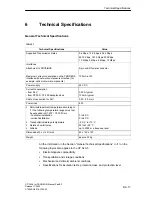
Страница 17: ... backplane bus 0 25 A typical 150 mA typical Cable cross section for 24V 0 25 2 5 mm2 Power loss 6 W S Permissible ambient temperature according to 1 the following temperature ranges must not be exceeded in S7 300 C7 300 tiers horizontal installation vertical installation S Transportation storage temperature S Relative humidity max S Altitude 0 to 60_C 0 to 40_C 40 C to 70 C 95 at 25 C up to 2000 ...

Отзывы: