4
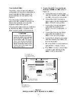
Figure 4
Wiring an ACM-1 that is Mounted on an MKB-2
To wire the ACM-1:
The ACM-1 can be wired in two different
configurations: One wiring configuration is
used if an MMB (or PSR) supplies the
power and data communications (See
Figure 4).
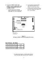
The other wiring configuration is used
where a PS-5N7 supplies the power and
data communications, as in a remote
expander board (See Figure 5).
The wiring information below is unaffected
by whether the ACM-1 module is in the
upper or lower position of the enclosure.
CAUTION:
Remember that all cables that con-
nect to the ACM-1 are polarized
and connect in one way only. DO
NOT FORCE THEM. The location
of pin 1 on a connector is indicated
by marks on the pin or by color
tracers on the wires. In Nos.1 and
2 below, be sure the black tracer
wire is close to the 1.
1. To wire the ACM-1 in an enclosure
that has an MMB or a PSR
(Refer to
Figure 4)
:
a. Connect the long 15-ribbon cable
(P/N 555-192238) from the MMB, P8
(or PSR-1, P5) to P5 on the ACM-1.
b. Connect the short 15-conductor
ribbon cable (P/N 555-192242) from
ANN-1, P3 to P4 on the ACM-1.
c. Connect the 14-conductor ribbon
cable (P/N 555-192236) from
TMM-1, P3 to P1 on the ACM-1, if
used.
d. Connect the 50-conductor ribbon
cable (P/N 555-192201) from
TBM-2, P3 to P2 on the ACM-1.
e. Connect the 5-conductor wire cable
(P/N 600-190220) from TBM-2, P2
to P3 on the ACM-1.
f.
P6 on the ACM-1 is connected to an
optional BTC-1 module, if used.
g. If an MMM-1 is used, connect the 9-
conductor cable attached to the
MMM-1 to P7 on the ACM-1.
P5
to MMB-
2
/-
3
,
P8
or to
PS
R-
1
,
P5
or to
P
IM-
1
,
P1
Ribbon
C
able
P
/
N 555
-
1
9
2238
Содержание ACM-1
Страница 7: ...7 ...


