Infrastructure and Mobility, Traffic Solutions
Sopers Lane, Poole, Dorset
BH17 7ER
Version
7
Page 25 of 76
Status
ISSUED
Last Editor
Ore Oluwatudimu
TS008468
Date
31/01/2017
Document
Name
UPS Solution General Handbook
Doc. No.
667/HB/47750/000
Copyright
Siemens plc 2017 All Rights Reserved
7 External Cabling Scheme
7.1 Mains Power Supply
All site installations should be designed in such a way that the controller cabinet, UPS
cabinet, Battery Expansion cabinet (if required) and feeder pillar (generator connect or
otherwise) are kept within the immediate vicinity of each other. Cable lengths between all
pillars and cabinets should be minimized wherever possible to reduce the impact of cable
losses.
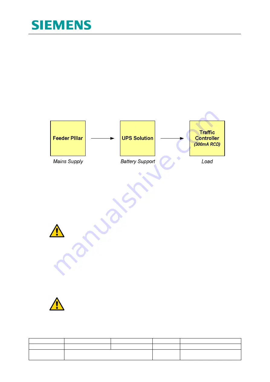
3 core mains cable is to be used for the following connections:
•
Mains supply within Feeder Pillar
à
UPS mains Input
•
UPS mains output
à
Traffic Controller Mains input
Figure 7-1: Mains Power Supply Chain
Cable size and length between the
feeder pillar
and
traffic controller
depend on the
controller fusing and expected voltage drop, as dictated in the following document:
667/HB/45040/000 – Isolators and Feeder Pillars General Handbook
The UPS cabinet can be installed in any location between the feeder pillar and controller
cabinet as long as the total cable length does not exceed the values specified in the
above document.
WARNING:
The same cable is to be used throughout the mains power supply
chain from feeder pillar to controller.
7.2 UPS Earthing and Fault Protection RCDs
When installed, the UPS solution relies upon the incoming earth from the DNO mains
supply via the Main Earth Terminal in the feeder pillar. All cabinets and poles within the
installation are equi-potentially bonded and earthed in this fashion.
However in the unlikely event that the supply earth is lost - e.g. a break in the supply
cable - the bonded cabinets and poles, all of which are in contact with the general mass
of earth, act as a rudimentary TT earth electrode.
WARNING:
It is therefore
necessary that a 300mA RCD is fitted at the
controller input
to provide automatic disconnection of supply if a Live-Earth
fault occurs while in this configuration.
This RCD is also required to make sure a UPS supported site complies with TT
installation requirements if the incoming earth is ever lost.


