page 2 of 2
A6V12688327
A5W00101286 RS-AC
Technical Manual
Decentralized Power Supply
JB 125C33, 160 mA, AC 110 – 277V
5WG1125-4CB33
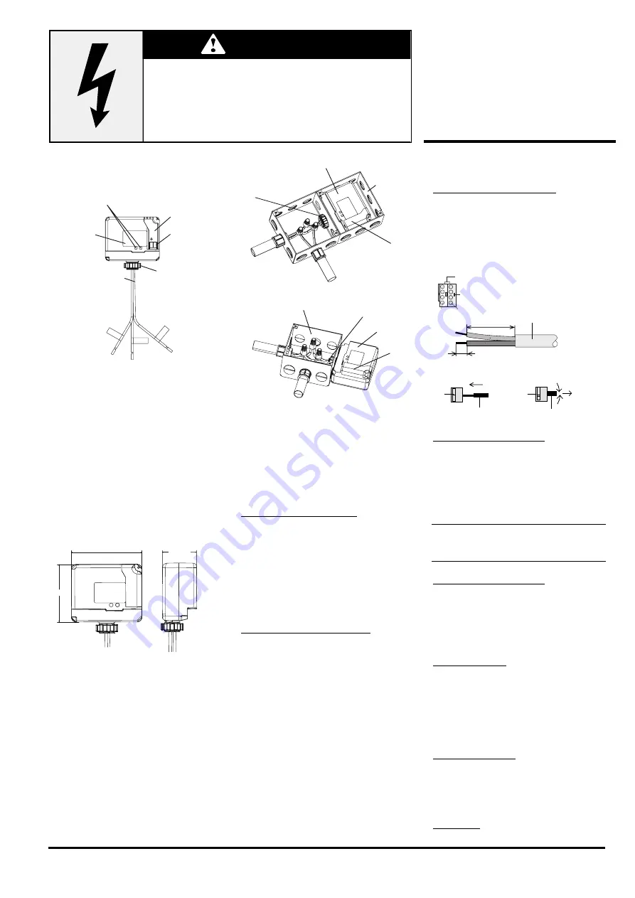
Location and Function of
Interface Elements
A1
A2
A3
A4
A5
A6
A1
Type label
A2
Protective lid over bus connection
A3
Bus connection terminal block for single core
conductors with Ø 0.6...0.8 mm
A4
Green LED for indicating KNX power
present (ON)
Red LED for indicating shorted-out bus line or
device over-load (OVERLOAD)
A5
1/2 inch screw nut
A6
Wire (black) line (hot)
(AWG #14)
Wire (white) neutral
(AWG #14)
Wire (green) ground
(AWG#14)
Dimension Diagram
Dimensions in mm (inch)
92 (3.62)
76 (3.0)
45 (1.76)
B4
B2
B1
B3
B4
B1
B2
B3
B1 Junction Box
B2 Device
B3 Bus connection pins of the module for connec-
tion of the bus terminal block for single core
conductors with Ø 0.6…0.8 mm
B4 1/2 inch screw nut
Mounting
Option 1 (mounting inside a J-Box):
- Insert the thread of the JB module (B2) into the 1/2
inch knockout between two adjacent J-Boxes (B1)
- Fasten the JB module (B2) with the 1/2 inch thread
nut (B4)
- Remove the protective lid (B3) and connect the
bus wire to the bus terminal block (A4)
- Connect the wires from the device to the field
wires using wire nuts (not provided in package)
Option 2 (mounting outside of a J-Box):
- Insert the thread of the JB module (B2) into the 1/2
inch knockout of the J-Box (B1)
- Fasten the JB module (B2) with the 1/2 inch thread
nut (B4) to the J-Box (B1)
- Connect the bus wire to the bus terminal block un-
der the protective cover (B3)
- Connect the wires from the device to the field
wires using wire nuts (not provided in package)
- Install the protective lid (B3) and fasten with
screws (provided in package)
Dismounting
- Disconnect power to the module
- Remove the wire nuts and bus connection
- Unfasten the 1/2 inch thread nut (B4) connecting
the JB module (B2) to the J-Box (B1)
- Remove the JB module (B2) from the J-Box (B1)
Wiring
Slipping off/on bus connection blocks
The bus connection block consists of two compo-
nents (C2.1 and C2.2) with four terminal contacts
each. Take care not to damage the two test sockets
(C2.3) by accidentally connecting them to the bus ca-
ble or with the screwdriver (e.g. when attempting to
unplug the bus connection block).
C2
C2.2 C2.1
C2.3
D2
D2.4
5 mm
D2
D2.4
25...35 mm
D1
Slipping off bus connection blocks
- Carefully put the screwdriver to the wire insertion
slit of the bus connection block’s grey component
(C2.2) and
- pull the bus connection block (C2) from the mod-
ule.
Note
Don’t try to remove the bus connection block from
the bottom side. There is a risk of shorting-out the
device!
Slipping on bus connection blocks
- Slip the bus connection block (C2) onto the guide
slot of the module and
- press the bus connection block (C2) down to the
stop.
Connecting and Disconnecting bus cables
Connecting bus cables
- The bus connection block (D1) can be used with
single core conductors Ø 0.6…0.8 mm.
- Remove approx. 5 mm of insulation from the con-
ductor (D2) and plug it into the bus connection
block (D1)
(red = +, grey = -)
Disconnecting bus cables
- Unplug the bus connection block (D1) and remove
the bus cable conductor (D2) while simultaneously
wiggling it.
Connecting mains:
Connect wires
Connect wire leads using wire nuts.
Hazardous voltage.
Can cause death, or serious injury or property damage.
The device must not be opened.
A faulty device should be returned to the local Siemens sales office
or distributor.
WARNING
WARNING
The device must be mounted and commissioned by a factory trained person.
The prevailing safety rules must be observed!
Mount in dry locations only!


