12 – 3
3ZW1012-0WL11-0AB1
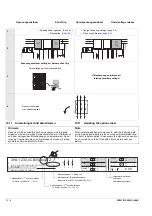
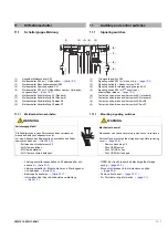
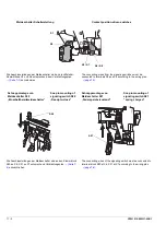
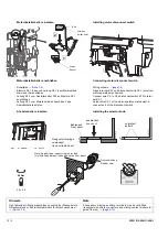
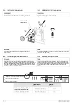
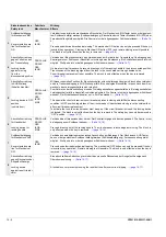
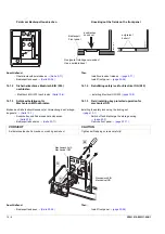
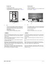
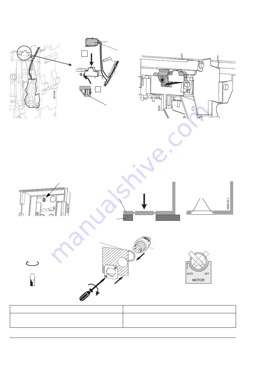
Installing motor disconnect switch
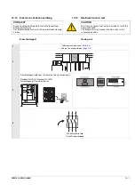
Connecting motor disconnect switch
- Wiring scheme
- Open terminal X5.1 and disconnenct wire X5-1 (wire from
motor-operated mechanism)
- Connect wire X5.1 of the disconnect switch S12 to termi-
nal X5.1.
- Solder wire X5-1 of the motor-operated mechanism to
connection 4 of the disconnect switch
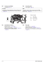
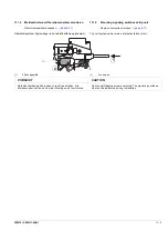
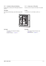
Installing the selector knob
entgraten!
deburr!
0045-01-2
ausbrechen
knock out
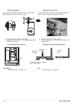
Bedienpult
Front panel
Geeignete Unterlage
verwenden!
Use a suitable base!
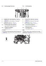
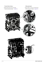
Motorabstellschalter einsetzen
Motorabstellschalter anschließen
- Schaltplan
- Klemme X5.1 lösen und Leitung X5-1 (vom Motorantrieb
kommend) herausziehen
- Leitung X5-1 vom Abstellschalter S12 an Klemme X5.1
anschließen
- Leitung X5-1 vom Motorantrieb an Anschluss 4 des
Abstellschalters anlöten
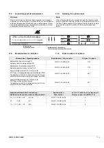
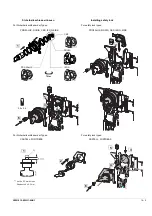
Knebelschalter einsetzen
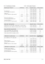
Hinweis
Note
Ggf. fehlende Hilfsstromanschlüsse nachrüsten (Messerleiste,
Hilfsstromstecker, Schleifkontaktmodul für Einschubrahmen).
→
If necessary missing auxiliary terminals may be retrofitted
(receptacle, auxiliary connectors and sliding contact module for
guide frames).
→
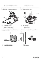
S 12
1
2
Lötstelle
Solder point
Wippe
Rocker
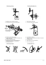
3.0 x 0.6
0.5 Nm
*XPPLGLFKWXQJ
5XEEHUVHDO
1RWH$QDGGLWLRQDOVSDFHUULQJLVSURYLGHG
,WLVLQVWDOOHGEHWZHHQWKHNQREDQGWKHIURQWSDQHO
Содержание 3ZW1012-0WL11-0AB1
Страница 15: ...3ZW1012 0WL11 0AB1 0 XV ...
Страница 87: ...3ZW1012 0WL11 0AB1 8 15 S Auslösung I Auslösung S tripping I tripping ...
Страница 88: ...8 16 3ZW1012 0WL11 0AB1 Erdschlussauslösung Ground fault tripping ...
Страница 251: ...3ZW1012 0WL11 0AB1 14 15 Arranging lock assembly Installing Schlossbaugruppe vormontieren Einbau 0767 1 2 3 4 6 5 ...
Страница 359: ...3ZW1012 0WL11 0AB1 27 5 ...
Страница 360: ...27 6 3ZW1012 0WL11 0AB1 ...
Страница 366: ......
Страница 367: ......

