8 – 108
3ZW1012-0WL11-0AB1
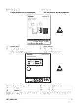
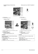
Test-Modus verlassen
Taste „TEST“ ca. 30 s nicht betätigen.
Sind alle LEDs eingeschaltet, wird der Test-Modus bereits nach ca.
1 s verlassen.
8.2.3.2 ZSI-Modul
Funktion
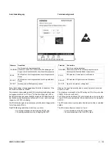
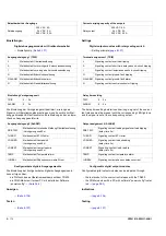
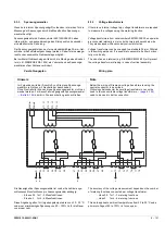
Die Kombination des Leistungsschalters mit einem ZSI-Modul (
Z
eit-
verzögerte
S
elektivitäts-
S
teuerung) erlaubt es, in Schaltanlagen mit
mehreren Staffelebenen einen auftretenden Kurzschluss genau zu
lokalisieren.
Dazu werden alle Leistungsschalter über ihr ZSI-Modul miteinander
verbunden.
Im Kurz- und/oder Erdschlussfall fragt jeder vom Kurzschlussstrom
durchflossene Leistungsschalter die ihm direkt nachgeordneten Lei-
stungsschalter ab, ob der Kurz- und/oder Erdschluss auch in der
nächsten untergeordneten Staffelebene auftritt. Es löst nur der, in
Energieflussrichtung gesehen, nächstgelegene, dem Kurz- und/
oder Erdschluss vorgeordnete Leistungsschalter aus.
Eine eingestellte Verzögerungszeit t
sd
für die Kurzschlussauslösung
wird auf 50 ms gesetzt bei Schalterstellung am ZSI-Modul „S“ oder
„S+G“, wenn der Leistungsschalter im Kurzschlussfall kein Blockier-
signal ZSI-IN von einem nachgeordneten Leistungsschalter erhält.
Bei einem erkannten Kurzschluss wird ein Blockiersignal ZSI-OUT
an die vorgeordneten Leistungsschalter ausgegeben. Die Kurz-
schlussauslösung erfolgt jedoch frühestens nach 50 ms, typisch
sind 80 … 90 ms.
Eine eingestellte Verzögerungszeit t
g
für die Erdschlussauslösung
wird auf 100 ms gesetzt bei Schalterstellung am ZSI-Modul „G“
oder „S+G“, wenn der Leistungsschalter im Erdschlussfall kein
Blockiersignal ZSI-IN von einem nachgeordneten Leistungsschalter
erhält. Bei einem erkannten Erdschluss wird ein Blockiersignal
ZSI-OUT an die vorgeordneten Leistungsschalter ausgegeben. Die
Erschlussauslösung erfolgt jedoch frühestens nach 100 ms, typisch
sind 130 ... 140 ms.
Zur Sicherheit wird nach längstens 3 s ein ausgegebenes Blockier-
signal ZSI-OUT beendet.
Das ZSI-Modul des Leistungsschalters SENTRON WL ist mit dem
ZSI-Modul der Leistungsschalter 3WN und 3WS sowie SENTRON
3VA funktionskompatibel.
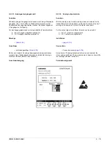
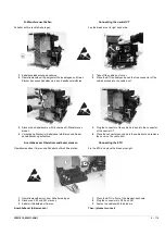
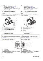
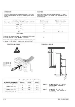
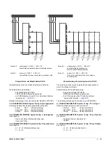
Montage
→
Anschluss
→
Es kann pro Leistungsschalter nur ein ZSI-Modul angeschlossen
werden.
Wird das ZSI-Modul zusammen mit anderen
c
-Modulen
verwendet, muss das ZSI-Modul direkt an das COM-Modul bzw.
den Handstecker X8 angeschlossen werden.
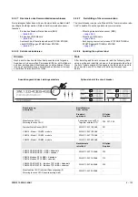
Quitting the test mode
Do not press the “TEST” button for approximately 30 seconds.
If all LED's are on, the test mode is already quitted after about 1 s.
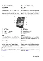
8.2.3.2 ZSI-module
Function
If the circuit breaker is combined with a ZSI-module, a short-circuit
occurring in systems with several grading levels can be localised
precisely.
For this purpose, all circuit breakers are interconnected via their
ZSI-modules.
When a short-circuit or ground-fault occurs, each circuit breaker
affected by the short-circuit or ground-fault current queries its down-
stream circuit breaker to determine whether the short-circuit or
ground-fault is present in the next downstream grading level. In the
direction of the energy flow, only the circuit breaker nearest to the
short-circuit or ground-fault in the upstream direction is tripped.
A possible delay time setting t
sd
for the short-circuit tripping is set to
50 ms if "S" or "S+G" is selected on the ZSI module and if in the
event of short-circuit the circuit breaker does not receive a blocking
signal ZSI-IN sent from its downstream circuit breaker. In case of a
detected short-circuit a blocking signal ZSI-OUT will be sent to the
preceeding circuit breakers. The trip does take place after 50 ms. It
typically delays between 80 and 90 ms.
A possible delay time setting for the ground-fault tripping is set to
100 ms if "G" or "S+G" is selected on the ZSI module and if in the
event of ground-fault the circuit breaker does not receive a blocking
signal ZSI-IN sent from its downstream circuit breaker.
In case of a detected ground-fault a blocking signal ZSI-OUT will
sent to the preceeding circuit breakers. The trip does take place
after 100 ms. It typically delays between 130 and 140 ms.
For safety reason after a maximum delay time of 3 s a given bloc-
king signal ZSI-OUT is terminated.
The ZSI-module of the circuit breaker SENTRON WL is function-
compatible with the ZSI-module of the circuit breakers 3WN and
3WS as well as the MCCB SENTRON 3VA.
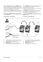
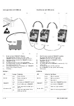
Installation
→
Connection
→
Only one ZSI-module can be connected per circuit breaker.
If the ZSI-module is used together with other
c
-modules,
the ZSI-module must be connected directly to the COM module or
hand plug X8.
Содержание 3ZW1012-0WL11-0AB1
Страница 15: ...3ZW1012 0WL11 0AB1 0 XV ...
Страница 87: ...3ZW1012 0WL11 0AB1 8 15 S Auslösung I Auslösung S tripping I tripping ...
Страница 88: ...8 16 3ZW1012 0WL11 0AB1 Erdschlussauslösung Ground fault tripping ...
Страница 251: ...3ZW1012 0WL11 0AB1 14 15 Arranging lock assembly Installing Schlossbaugruppe vormontieren Einbau 0767 1 2 3 4 6 5 ...
Страница 359: ...3ZW1012 0WL11 0AB1 27 5 ...
Страница 360: ...27 6 3ZW1012 0WL11 0AB1 ...
Страница 366: ......
Страница 367: ......

