background image

4

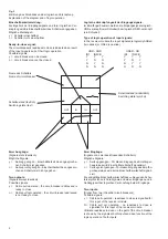
Schaltzustand (sinnbildlich)
Switching state (symbol)

Name des Schalters
Name of circuit-breaker

Zwei Ausgänge:
(Signale stets identisch)
Mögliche Signale:
y =

Seilzug gezogen - Einschaltbarkeit des angesproche-
nen Schalters ist gegeben

n =

Seilzug nicht gezogen - Einschaltbarkeit des angespro-
chenen Schalters ist nicht gegeben

Two outputs:
(Signals always identical)
Possible signals:
y =

Cable pull operated - the circuit-breaker addressed is
ready to close

n =

Cable pull not operated - the circuit-breaker addressed
is not ready to close

Zwei Eingänge:
(Signale von zwei beeinflussenden Schaltern)
Mögliche Signale:
y =

Seilzug gezogen - Für diesen Eingang des Empfänger-
bausteines wird Einschaltbereitschaft signalisiert.

n  =

Seilzug nicht gezogen - Für diesen Eingang des Empfän-
gerbausteines wird keine Einschaltbereitschaft signali-
siert.

Die endgültige Einschaltbereitschaft des vorliegenden Schal-
ters ergibt sich durch die Signale an beiden Eingängen und in
Abhängigkeit der logischen Verknüpfung beider Eingänge.

Two inputs:
(Signal from two influential circuit-breakers)
Possible signals:
y =

Cable pull operated - readiness to close is signalled for
this input of the receiver module.

N = Cable pull not operated - no readiness to close is

signalled for this input of the receiver module.

Ultimate readiness to close on the part of the circuit-breaker
is shown by  the signals at both inputs and as a function of the
logic operation of both inputs.

Schaltzustand (textlich)
Switching state (text)

IN

IN

OUT

OUT

Einschaltbarkeitsmeldung:
Als Ergebnis der Eingangssignale und ihrer logischen Ver-
knüpfung wird die Einschaltbarkeit des Schalters angegeben.
Mögliche Meldungen:
y = Schalter einschaltbar
n = Schalter nicht einschaltbar

Ready-to-close signal:
The circuit-breaker's readiness to close is indicated as a result
of the input signals and of their logic operation.
Possible signals:
y = circuit-breaker can be closed
n = circuit-breaker cannot be closed

Logische Verknüpfungsart der Eingangssignale:
Im Empfängerbaustein werden die Eingangssignale logisch-
UND-verknüpft (zwei Schieber) bzw. logisch-ODER-verknüpft
(ein Schieber).

Type of logic operation of input signals:
In  the  receiver  module  the  input  signals are  logically ANDed
(two slides) or ORed (one slide).

   UND - AND
IN1

IN2CB

Y

Y

Y

Y

N

N

N

Y

N

N

N

N

   ODER - OR
IN1

IN2CB

Y

Y

Y

Y

N

Y

N

Y

Y

N

N

N

Erklärung des Sinnbildes und der logischen Verknüpfung
Explanation of the diagram and of logic operation

Fig. 3

Содержание 3WX31 46-7C1 3 Series

Страница 1: ...rperver letzung oder erheblicher Sachschaden die Folge sein 3WX31 3WX35 Alle Rechte vorbehalten All rights reserved Siemens AG 1994 3WN 3WN Betriebsanleitung Operating Instructions Bestell Nr Order No 3ZX1812 0WX31 6DN0 9239 9721 174 Hazardous voltage Before starting work isolate device and secure against reclosing Only qualified personnel may perform installation and assembly work Non observance ...

Страница 2: ... 3 24 Einstellung des Stößels am Schalter 9 4 Funktionsprüfung 11 5 Wartung und Instandhaltung 11 Contents 1 Introduction 3 1 1 Mutual interlocking design variants 3 1 2 Realizable combinations 3 2 Function description of 3 2 circuit breaker interlocking 3 Assembly steps 9 3 1 Installation instructions for the cable pulls 9 3 2 Installing the cable pulls 9 3 21 Installation instructions for the ca...

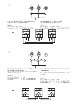
Страница 3: ...der logischen Verknüpfung Fig 4 Nur ein Schalter von dreien einschaltbar Wenn ein Schalter eingeschaltet ist können die anderen beiden Schalter nicht eingeschaltet werden Dazu werden 3 UND Schalter gegeneinander verriegelt Fig 5 Schalter B ist nur einschaltbar wenn Schalter A1 und A2 ausgeschaltet sind Schalter A1 und oder A2 sind nur ein schaltbar wenn Schalter B ausgeschaltet ist Dazu wird ein U...

Страница 4: ...is signalled for this input of the receiver module N Cable pull not operated no readiness to close is signalled for this input of the receiver module Ultimate readiness to close on the part of the circuit breaker is shown by the signals at both inputs and as a function of the logic operation of both inputs Schaltzustand textlich Switching state text IN IN OUT OUT Einschaltbarkeitsmeldung Als Ergeb...

Страница 5: ... B G A1 A2 Fig 5 Schalter A1 und oder A2 können nur eingeschaltet werden wenn Schalter B ausgeschaltet ist Schalter B kann nur eingeschaltet werden wenn Schalter A1 und A2 ausgeschaltet sind Bestellung Schalter A1 A2 und B z S52 Einschub A1 und A2 G bzw K 15 Stelle MLFB Einschub B J bzw M 15 Stelle MLFB Circuit breaker A1 and or A2 can be closed only if circuit breaker B is open Circuit breaker B ...

Страница 6: ...ann nur eingeschaltet werden wenn Schalter B ausgeschaltet ist Schalter B kann nur eingeschaltet werden wenn Schalter A ausgeschaltet ist Bestellung Schalter A und B z S52 Einschub A und B G bzw K 15 Stelle MLFB z B Circuit breaker A can be closed only if circuit breaker B is open Circuit breaker B can be closed only if circuit breaker A is open Ordering Circuit breaker A und B z S52 Withdrawable ...

Страница 7: ...tion description of 2 circuit breaker inter locking The function principle of mechanical interlocking is des cribed in the following taking the example of the variant mutual interlocking of two circuit breakers as shown in Fig 7 i e the combination of two withdrawable units of interlock ing version a see page 6 Version b OR element differs only in the number of available cable pulls Version c like...

Страница 8: ...8 Fig 8 5 12 9 7 3 8 4 6 13 ...

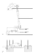
Страница 9: ...ßel am Schalter sind werkseitig justiert 3 Assembly steps 3 1 Installation instructions for the cable pulls Cable pulls must be kept clear of all live parts or suitably insulated The respective permissible cable pull length depends on the number and magnitude of the bending radii With a given tensile force compensation is possible only by reducing the cable pull length For example in the case of d...

Страница 10: ...10 Fig 9 Fig 10 16 15 14 5 3 2 1 4 eingeschaltet closed ausgeschaltet open ...

Страница 11: ...pull is moved by its tension spring into the front end position The relevant circuit breaker is shut down or cannot be closed 4 Funktionsprüfung Beide Einschübe gegebenenfalls unter Drücken des Gebers in die Trennstellung bringen Schalter einschieben und in die Betriebsstellung fahren da Funktion nur dort möglich ist Schalter A einschalten Schalter B darf sich elektrisch nicht einschalten lassen u...

Страница 12: ...ublished by the Power Transmission and Distribution Group Schaltwerk Berlin D 13623 Berlin Federal Republic of Germany Subject to change Bestell Nr Order No 3ZX1812 0WX31 6DN0 9239 9721 174 Bestell Ort Place of Order SW PVZ Berlin Printed in the Federal Republic of Germany AG 02 95 0 1 SW De En Siemens Aktiengesellschaft ...

Отзывы: