3ZX1012-0RW40-2DA1
7
English
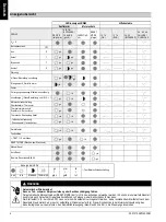
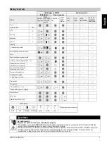
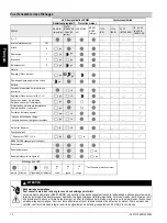
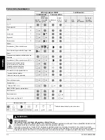
Display overview
LED displays on 3RW40
Auxiliary contacts
Soft starter
Motor protection
3RW40
DEVICE
(rd/gn/ylw)
STATE /
BYPASSED
/ FAILURE
(gn/rd)
OVERLOAD
(rd)
RESET
MODE
(ylw/gn)
13 14
(ON)
13 14
(RUN)
24 23
(BYPASSED)
96 95 98
FAILURE /
OVERLOAD
U
s
= 0
Operating state
IN
OFF
0
Start-up
1
Bypassed
1
Run-out
0
Warning
I
e
/ class setting invalid
Start-up locked, device too warm
Error
Supply voltage electronics invalid
Invalid I
e
/ class setting and IN (0 -> 1)
Motor protection switch-off
Overload relay / thermistor
Thermistor motor protection
Wire break / short circuit
Thermal overload device
- Missing load voltage
- Phase failure, no load
Device fault
Test function
1)
Press TEST for t > 5 s
RESET MODE (press to change)
Manual Reset
Auto Reset
Remote Reset
s
ee Fig. 6.2
LED display
1)
Motor protection shutdown test
gn
=
ylw
=
rd
=
OFF
ON
flashing flickering
green
yellow
red
WARNING
Automatic restart.
May result in death, serious injury or damage to property.
The automatic reset mode (RESET MODE) must not be used in applications where an unexpected restart of the motor after the
recovery time has elapsed may lead to personal injury or damage to property.
The start command (e.g. by the PLC) must be reset before a reset command, since an automatic restart is executed when a start
command is pending after the reset command. This especially applies to motor protection tripping. For safety reasons it is
recommended to integrate the group fault output (terminals 95 and 96) into the control.
gn
gn
gn
gn
gn
gn
gn
gn
gn gn
ylw
rd
gn
rd
gn
gn
ylw
rd
gn
rd
rd
rd
gn
rd
ylw
gn
!


