background image


Replacement parts 


8.8 Pulse encoder 

A5E01083943A AB       
Siemens AG Operating Instructions 2.02 1FW4  

97


8.8


Pulse encoder 

Replacement parts 


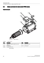
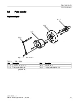
Figure 8-6 

Pulse encoder 

Table 8-6 

Pulse encoder 

Part 

Description 

Part 

Description 

55.10 

Tachometer/speed sensor 

55.21 

Adapter flange 

55.32 

Shaft journal (with cone) 

55.63 

Torque transmission element 

[ID 1137.00] 

Содержание 1FW4

Страница 1: ...Three phase synchronous motor HT direct Type 1FW4 Operating Instructions 01 2009 ht direct ...

Страница 2: ...14 01 2009 16 26 ...

Страница 3: ...tion technical data 2 Transport installation and assembly 3 Commissioning 4 Operation 5 Maintenance 6 Disposal and recycling 7 Replacement parts 8 Three phase synchronous motor HT direct 1FW4 Operating Instructions Edition 01 2009 ...

Страница 4: ...rmed by qualified personnel Within the context of the safety notes in this documentation qualified persons are defined as persons who are authorized to commission ground and label devices systems and circuits in accordance with established safety practices and standards Proper use of Siemens products Note the following WARNING Siemens products may only be used for the applications described in the...

Страница 5: ...4 air cooled version rating plate 27 2 7 Definitions of the electrical data 29 2 8 Technical design 32 2 9 Cooling 34 2 9 1 Water cooling 34 2 9 2 Air cooling 37 3 Transport installation and assembly 39 3 1 Transportation and storage 39 3 2 Protection of the cooling water ducts for the water cooled version 40 3 3 Installation 41 3 4 Aligning 43 3 5 Mounting 45 3 6 Insulated bearings 45 3 7 Connect...

Страница 6: ...Regreasing intervals for rolling contact bearings grease type 73 6 1 4 Servicing the external fan 74 6 1 5 Cleaning the heat exchanger 75 6 2 Servicing inspections 75 6 2 1 Servicing instructions 75 6 2 2 First service after installation or repair 76 6 2 3 General inspection 76 6 3 Corrective Maintenance 77 6 3 1 Changing the bearing 77 6 3 2 Replacing the sensor for the water cooled 1FW4 motor 78...

Страница 7: ...ts of the water quality 35 Table 2 10 Derating factors AS a function of the ambient temperature and site altitude 37 Table 3 1 Permissible deviations 44 Table 3 2 Tightening torques of bolts cable lug 49 Table 3 3 Tightening torques of bolts ground terminals 49 Table 3 4 Terminal designations with the 1U1 1 as an example 52 Table 4 1 Insulation resistance at 25 C 61 Table 5 1 Fault table electrica...

Страница 8: ...nection of the power cable in the main terminal box 51 Figure 3 5 Direction of rotation of the motor when looking at the drive end 52 Figure 3 6 Strain relief device and sealing insert 54 Figure 6 1 Detailed view of the speed sensor for the water cooled 1FW4 motor 78 Figure 6 2 Replacing the sensor for the water cooled 1FW4 motor 79 Figure 6 3 Detailed view of the speed sensor for the air cooled 1...

Страница 9: ...e connecting cable When working on the drive system you must prevent any rotational movement of the motor shaft Dangerous voltage via the converter WARNING Dangerous voltage via the converter As long as the feeding converter is switched on or the DC link of the converter is not discharged there can be a voltage at the motor terminals even when the rotor is not moving Depending on the type of conve...

Страница 10: ...ation commissioning maintenance and repairs are carried out by qualified persons and checked by responsible suitably skilled persons these instructions and the motor documentation are made available at all times while work is in progress the technical data and specifications relating to the permissible installation connection ambient and operating conditions are taken into account at all times the...

Страница 11: ...ty as per EN 50082 ID 837 01 1 4 Magnetic fields of 1FW4 motors Safety information For 1FW4 series motors in the assembled state the field of the permanent magnets is channeled through the iron circuit of the motor As a result no harmful magnetic field can be detected outside of the motor in accordance with EN 50061 WARNING Danger posed by magnetic fields when motor is open The permanent magnet ro...

Страница 12: ...tic fields can interfere with electronic devices This can cause them to malfunction Ensure that no electronic devices are located in the area of the magnetic field CAUTION Risk of data loss Magnetic fields can cause loss of data on magnetic or electronic data media Do not carry any magnetic or electronic data media with you ID 1146 00 See also SIEMENS Service Center Page 23 ...

Страница 13: ...Safety information 1 5 EC Declaration by the Manufacturer A5E01083943A AB Siemens AG Operating Instructions 2 02 1FW4 11 1 5 EC Declaration by the Manufacturer ...

Страница 14: ...Safety information 1 5 EC Declaration by the Manufacturer A5E01083943A AB 12 Siemens AG Operating Instructions 2 02 1FW4 ...

Страница 15: ...Safety information 1 5 EC Declaration by the Manufacturer A5E01083943A AB Siemens AG Operating Instructions 2 02 1FW4 13 ...

Страница 16: ...Safety information 1 5 EC Declaration by the Manufacturer A5E01083943A AB 14 Siemens AG Operating Instructions 2 02 1FW4 ...

Страница 17: ...Safety information 1 5 EC Declaration by the Manufacturer A5E01083943A AB Siemens AG Operating Instructions 2 02 1FW4 15 ...

Страница 18: ...Safety information 1 6 EU Declaration of Conformity 73 23 EEC A5E01083943A AB 16 Siemens AG Operating Instructions 2 02 1FW4 1 6 EU Declaration of Conformity 73 23 EEC ...

Страница 19: ...Safety information 1 6 EU Declaration of Conformity 73 23 EEC A5E01083943A AB Siemens AG Operating Instructions 2 02 1FW4 17 ...

Страница 20: ...Safety information 1 6 EU Declaration of Conformity 73 23 EEC A5E01083943A AB 18 Siemens AG Operating Instructions 2 02 1FW4 ...

Страница 21: ...Safety information 1 6 EU Declaration of Conformity 73 23 EEC A5E01083943A AB Siemens AG Operating Instructions 2 02 1FW4 19 ...

Страница 22: ...Safety information 1 6 EU Declaration of Conformity 73 23 EEC A5E01083943A AB 20 Siemens AG Operating Instructions 2 02 1FW4 ...

Страница 23: ...Safety information 1 6 EU Declaration of Conformity 73 23 EEC A5E01083943A AB Siemens AG Operating Instructions 2 02 1FW4 21 ...

Страница 24: ......

Страница 25: ...Phone 1 423 262 2522 Asia China Phone 86 1064 719 990 E Mail support automation siemens com Internet English www siemens com automation support request Internet Deutsch www siemens de automation support request ID 302 02 2 2 Field of application overview The series 1FW4 motors are multi pin permanent magnet synchronous motors with full shaft rotors The motors are available in liquid cooled or air ...

Страница 26: ...rsh environment containing unusually large quantities of dust acids corrosive substances or gases CAUTION Destruction of the motor If you connect the motor directly to the electrical power supply it may be destroyed The motor may only be operated with a frequency converter Figure 2 1 1FW4 water cooled motor Figure 2 2 1FW4 air cooled motor ID 1147 00 ...

Страница 27: ...Motor design Overview The 1FW4 series motors are 3 phase synchronous motors of enclosed design with an internal cooling air circuit The fan impeller for the inner cooling air flow is mounted on the motor shaft Sensors are installed in the stator winding for monitoring the temperature In accordance with the options ordered various supplementary devices can be installed or attached e g anti condensa...

Страница 28: ...8 Noise emission IEC EN 60034 9 Mechanical vibrations IEC EN 60034 14 IEC standard voltages IEC DIN IEC 60038 Entry to terminal box DIN 42925 Vibration limits DIN ISO 10816 Procedure for measuring the airborne noise emission DIN EN ISO 1680 The data regarding the actual degree of protection cooling and the construction type should be taken from the rating plate ID 1129 00 2 5 1FW4 water cooled ver...

Страница 29: ...5 Temperature class 15 Rated current A 6 Degree of protection 16 Rated frequency Hz 7 Rated torque Nm 17 Rated voltage V 8 Rated speed 1 min 18 Required amount of cooling water l min at the maximum cooling water inlet temperature C 9 Power factor 19 Maximum water pressure bar 10 Motor weight t ID 804 02 2 6 1FW4 air cooled version rating plate rating plate 9 SIEMENS 6 N FRV PLQ 1P 3 0 1 50 1 1 UQE...

Страница 30: ... 1 Motor type Three phase motor 10 Motor weight t 2 Motor type Synchronous motor order number 11 Maximum operating speed RPM 3 Serial number 12 Mode 4 Type of construction 13 Rotors standards and regulations 5 Temperature class 14 Rated output kW 6 Degree of protection 15 Rated current A 7 Rated torque Nm 16 Rated frequency Hz 8 Rated speed 1 min 17 Rated voltage V 9 Power factor ID 1131 00 ...

Страница 31: ...RLQW DVH VSHHG UDQJH LHOG ZHDNHQLQJ UDQJH 6 GXW 0 0 PD 0 0 1 Q Q 1 Q 3 NRQVW M Torque Mmax Maximum torque M MN Torque rated torque MN Rated torque S1 duty Continuous Duty P const Constant power nN Rated speed n nN Speed rated speed Figure 2 5 Speed torque characteristic for 1FW4 motors Voltage limiting characteristics As the speed of the permanent magnet rotor increases the counter voltage of the ...

Страница 32: ...ized in this fashion Rated speed nN The rated speed establishes the characteristic speed range for the motor in the speed torque diagram The motors can be operated above the rated speed range The speed range that is secured with the characteristic technical data lies between nN and a maximum of 1 2 x nN Stall torque M0 The static torque M0 is the thermal limit torque when the motor is static corre...

Страница 33: ...of 25 C kT MN IN Voltage constant kE value for an average winding temperature rise of 20 K The voltage constant kE is the value of the induced motor voltage relative to 1 000 rpm at 25 C coolant temperature liquid cooled or 40 C air cooled The phase to phase RMS motor terminal voltage is specified for the 1FW4 motors Winding resistance Rph The resistance of a phase at a room temperature of 20 C is...

Страница 34: ...tic current I 0 3 7 5 Electrical time constant Tel 5 10 Torque constant kT 3 7 5 Voltage constant kE 3 7 5 Winding resistance Rph 5 10 Moment of inertia Jmot 2 10 Temperature specifications The insulation of the motors is rated according to temperature class 155 previously F The generally permissible coolant temperatures of 25 C for water cooled 1FW4 motors and 40 C for the forced ventilated 1FW4 ...

Страница 35: ...e A rms value 2 3 mm s Permissible vibration speed1 Optional vibration severity grade B rms value 1 5 mm s Bearings Deep groove ball bearing with lubricating and re lubricating device connection One or two terminal boxes for power cables Auxiliary terminal boxes optional Sensor signal Directly on the sensor water cooled Auxiliary terminal box on external fan cowl forced ventilation Installation al...

Страница 36: ...ided for cooling on the cooling circuit The cooling duct geometry is designed so that the stator power losses are dissipated Forced air ventilation prevents local temperature peaks inside the motor This also draws off the low magnetic losses in the rotor via the stator Materials used in the cooling circuit CAUTION Damage due to sea water The water cooled housing is made of St37 steel This material...

Страница 37: ...ply temperature to 25 C 30 C 35 C 40 C 45 C Ambient temperature up to 40 C 45 C 50 C 55 C 60 C Derating factor kT 1 0 0 97 0 95 0 92 0 89 Cooling volumetric flow and water pressure Table 2 8 Cooling volumetric flow and maximum permissible water pressure per shaft height Shaft height Cooling volumetric flow Maximum permissible water pressure 1 Thread sizes for water connections 40 30 l min 5 bar G ...

Страница 38: ... particular ambient conditions Recooling unit The use of a correspondingly dimensioned recooling unit guarantees the coolant supply temperature of 25 C You can operate several motors and or the converter on one recooling unit The use of a closed cooling circuit is recommended Note Recooling unit not included in scope of delivery The recooling unit is not part of the motor s scope of delivery ཱ ི ཱི...

Страница 39: ... designed in accordance with EN 60034 1 for operation up to a coolant temperature of 40 C assuming compliance with all of the motor data If you operate the 1FW4 motor in higher ambient temperatures and or install it at altitudes higher than 1 000 m above sea level you must reduce the specified rating torque of the motor using the kHT factor In doing this note the derating factors in the following ...

Страница 40: ......

Страница 41: ...nly be stored in a temperature range from 20 C to 70 C For water cooled versions you must Drain the water for temperatures below 0 C and flush the cooling ducts with anti freeze emulsion Seal the water connections with threaded plugs Storing outdoors Choose a dry storage location which is safe from flooding and free from vibrations Repair any damage to the packaging before putting the equipment in...

Страница 42: ...s taken so that they can be reversed before the motors are put back into service Always slightly heat the motor windings Ensure forced air ventilation CAUTION Condensation water The motor is equipped with condensation water drain holes Regularly remove the screw plugs Allow the condensation water to drain and then replace the screw plugs ID 812 01 See also Stoppages Page 68 3 2 Protection of the c...

Страница 43: ...at the cooling system has been completely drained Drain the cooling ducts Blow out the cooling ducts with compressed air ID 1130 00 3 3 Installation Instructions relevant to safety CAUTION High surface temperature The surfaces of the 1FW4 motors can have temperatures 80 C This is the reason that temperature sensitive components e g cables or electronic components may neither be in contact nor be a...

Страница 44: ...arately Ensure that the output element has the correct type of balancing Power output elements may only be fitted or removed using suitable equipment CAUTION Feather key falling out The feather keys are only locked against falling out during shipping If the motor has two shaft ends and a power output element is only fitted to one end you must take steps to secure the feather key at the other end I...

Страница 45: ...rrectly align and securely mount the equipment These measures include Preparing the foundation Assembling the coupling Measuring the concentricity and axial eccentricity tolerances Positioning If personnel are not familiar with the necessary measures and procedures we recommend using the services of the local SIEMENS service center Position The following measures are required in order to compensat...

Страница 46: ...during operation The balance condition of the shaft full key or half key balancing and alignment errors primarily affect the service life of the bearing especially under high motor speeds or when using rigid couplings Perform the fine adjustments with plates under the entire motor foot KR H K ෙK K KR ཱ 1 Plates placed under the motor for alignment 2 Read alignment Figure 3 1 Aligning the motor Tab...

Страница 47: ...dging the bearing insulation The 1FW4 motors are fitted with electrically insulated bearings on the NDE CAUTION Bearing damages The bearing insulation must not be bridged Damage may be caused to the bearings if there is a flow of current ID 840 01 3 7 Connecting the cooling water supply for water cooled motors Connection The size of the connecting threads is described in this documentation in Chap...

Страница 48: ...to see whether the cooling water supply is airtight The maximum pressure must not be exceeded The maximum permissible pressure can be found on the motor rating plate If you do not then put the motor into operation you must implement the necessary measures during work stoppages ID 1142 00 See also Stoppages Page 68 3 8 Connection to the converter General Set 2 5 kHz as the converter pulse frequency...

Страница 49: ... bearings due to a flow of current If you want to prevent damage due to bearing currents you must take the entire system into account i e the motor converter and driven machine The following measures help to prevent bearing currents In addition to grounding the motors via the grounding conductor supplement the RF grounding with braided flat copper cables or RF stranded conductors Ensure that the c...

Страница 50: ...verter output The Siemens sales representative is responsible for selection and dimensioning Limit the rise in voltage by using output filters This dampens the harmonic content in the output voltage Use the motor reactors Give preference to an IT system with an insulated neutral point Note Operating instructions for the frequency converter The operating instructions for the frequency converter are...

Страница 51: ...e cable lug or strap of 10 mm is not undershot the minimum required screw in depth and the tightening torque for the clamping bolts as given in the following table are observed These differ depending on whether cable lugs or ground terminals are used Table 3 2 Tightening torques of bolts cable lug Bolt Screw in depth Tightening torque M12 x 25 16 mm 38 Nm M16 x 35 20 mm 92 Nm Table 3 3 Tightening ...

Страница 52: ... it has been locked out and secured so that it cannot be switched back on again Check that no voltage is present before commencing work The type designation of the terminal box for connecting the power cables can be found in the Technical specifications section see Main terminal box in the spare parts list for a diagram of the terminal box Connecting cables can be sealed and secured at every entry...

Страница 53: ... associated tightening torques for the main terminals can be found in the following representation 5DWHG LQVXODWLRQ YROWDJH GGLWLRQDO FRQYHUWHU SHDN YROWDJH 1XWV IRU OXJ SDUW 7HUPLQDO ER W SH 6XSSO FDEOH FRQGXFWRU FURVV VHFWLRQ WKDW FDQ EH FRQQHFWHG SRVVLEO UHGXFHG E WKH VL H RI WKH FDEOH HQWU 7KUHDG VL HV WLJKWHQLQJ WRUTXHV IRU SDUW QR ROWV IRU PDLQ WHUPLQDOV 3HDN YROWDJH SKDVH WR JURXQG DQG SKDV...

Страница 54: ...e of motor design and result for example from the use of unidirectional fans Any restrictions in terms of the direction of rotation resulting from the installation itself are not shown in the information on the rating plate and need to be considered separately when making the connections Terminal designations The following definitions apply in principle to the terminal designations of three phase ...

Страница 55: ...ion NOTICE If terminal links are used the current carrying connection is guaranteed using CuZn contact nuts These nuts must not be replaced by parts made from other materials Aluminum conductors If aluminum conductors are connected we recommend removing the oxide coating layer using a brush or file prior to inserting them in the clamps The conductors should then be immediately greased using neutra...

Страница 56: ...able diameter If the cable diameter is too small this should be increased by applying a layer of suitable sealing tape around the conductor After inserting the seal make a termination to match the cable and connect a grounding cable to it If the cable has external armoring do not route it directly into the terminal box but just up to the strain relief device which in this case should also be fitte...

Страница 57: ...the air gaps between non insulated parts are maintained 8 mm to 500 V 10 mm to 660 V and 14 mm to 1000 V Pay attention to protruding wire ends the connecting cables are laid in an open arrangement so that the cable insulation cannot be damaged during operation The machine is connected in accordance with the specified direction of rotation the inside of the terminal box is clean and free of any cab...

Страница 58: ...rminals are suitable for conductor cross sections up to 4 mm2 When choosing the connecting cables take into account the rated current and the plant specific conditions e g ambient temperature routing type etc to IEC EN 60204 1 Cable entry and routing For feeding in the connecting cables a two part cable inlet support with rubber seals is screwed onto the terminal box as standard Ensure that the IP...

Страница 59: ...the arrow indicating the direction of rotation The fan impeller is visible through the air inlet opening in the fan cowl on the motor If the direction of rotation is incorrect this can be changed by swapping over two of the phase conductors in the terminal box of the fan motor Connection Connect the fan motor in accordance with its terminal connection diagram located in the associated terminal box...

Страница 60: ......

Страница 61: ...tion on the motor and in these operating instructions The electrical data sheet The motor dimension drawing The shaft dimension drawing The test certificates The commissioning instructions for the converter Operational electrical equipment and motors have parts and components which are at hazardous voltage levels WARNING Driving the motor via the system If it is possible when operating the system ...

Страница 62: ...e feeding converter is switched on or the DC link of the converter is not discharged there can be a voltage at the motor terminals even when the rotor is not moving Depending on the type of converter the voltage can be up to 1 000 V Ensure that the five safety rules are complied with before working on the motor 1 Isolate 2 Protect against reconnection 3 Make sure that the equipment is de energized...

Страница 63: ...re the insulation resistance of the winding to the motor housing when the winding temperature is between 20 and 30 C Other values for the insulation resistance apply at different temperatures When measuring wait until the final resistance value is reached This is the case after approx 1 minute Limit values for stator winding The following table indicates the measuring circuit voltage and the limit...

Страница 64: ...ed voltage of 3 3 kV 3 3 kV x 5 MΩ kV 16 5 MΩ NOTICE Critical insulation resistance If the critical insulation resistance is reached or undershot the windings must be dried Please note that once the windings have been dried the insulation resistance of warm windings is lower You can only properly assess the insulation resistance after conversion to the reference temperature of 25 C NOTICE Measured...

Страница 65: ...the specified torque all touch protection measures for moving and live parts have been taken if the second end of the shaft is unused its featherkey has been secured so that it cannot fall out and the open shaft end is covered the cooling circuit is connected and ready for operation in the case of the liquid cooled version Please check that the cooling water system is switched on water of the conf...

Страница 66: ... that the impeller rotates freely Briefly switch the motor on and back off to compare the actual direction of rotation of the fan with the direction specified by the arrow Reverse the poles of the motor if the direction of rotation is incorrect Wrong direction of rotation of the fan leads to overload and premature failure ID 632 01 4 6 Monitoring the temperature of the stator winding Measures In a...

Страница 67: ...e frame foundation etc If the motor runs perfectly in terms of its mechanical operation switch on any present cooling devices external fan water cooler or similar and continue to monitor the motor for a while as it idles If the motor runs perfectly connect a load Check that it runs smoothly and read off and document the values for voltage current and power As far as possible read off and document ...

Страница 68: ... cooled motors Measures during de energizing If the corresponding control action does not take place automatically switch on the anti condensation heating if present You must not switch on the anti condensation heating until at least one hour after the motor has been switched off This prevents damage to the winding insulation ID 618 02 ...

Страница 69: ...tating parts from being touched or which are necessary to ensure correct air guidance and thus effective cooling remain closed during operation WARNING Faults in operation All deviations from normal operation e g higher power consumption higher temperatures or vibration levels unusual noises or odors tripped monitoring devices etc are indications that the motor is no longer functioning correctly I...

Страница 70: ...osion mothballing packaging and drying measures Switching on the anti condensation heating If anti condensation heating is available it can only be switched on 1 hour after the motor has been shut down This prevents damage to the winding insulation and the formation of condensation water ID 839 01 See also Transportation and storage Page 39 Measures to be performed prior to start up Page 62 Protec...

Страница 71: ...turer X X Rotor partially demagnetized Repair after consultation with manufacturing plant X Wrong direction of rotation of the external fan Check connections 1 Apart from eliminating the cause of the fault as described under Remedial measures you must also rectify any damage the motor may have suffered Mechanical faults Table 5 2 Fault table mechanical causes ULQGLQJ QRLVH LJK WHPSHUDWXUH ULVH 5DG...

Страница 72: ... QRLVH LJK WHPSHUDWXUH ULVH 5DGLDO YLEUDWLRQV LDO YLEUDWLRQV Possible causes of faults Remedial measures1 1 Apart from eliminating the cause of the fault as described under Remedial measures you must also rectify any damage the motor may have suffered 2 Take any changes into account for heating up ID 829 01 ...

Страница 73: ...mens Service Center DANGER Strong magnetic fields can directly affect persons and cause damage Observe the national and local regulations of your country The BGR B11 Electromagnetic Fields must be observed in the Federal Republic of Germany Observe all requirements The handling of components containing permanent magnets is strictly prohibited for all persons with pacemakers metallic implants and f...

Страница 74: ...s make sure that the system has been isolated from the power supply in accordance with the regulations Pay particular attention to the main circuits and also ensure that any supplementary and auxiliary circuits are also de energized and in particular the anti condensation heating Maintenance work may only be carried out when the motor is stationary Note the protection concept in the product catalo...

Страница 75: ...ngs must be regreased ahead of schedule during the main inspection For the standard range of applications a grease for temperatures down to 20 C is normally used for the initial greasing of the bearings The amount of grease for the initial lubrication is 25 to 35 of the free bearing volume You must not run the motor for a long period of time at speeds less than 10 rpm because no lubricating film w...

Страница 76: ...t the space for the spent grease has been over filled ID 1144 00 6 1 4 Servicing the external fan Preparatory steps WARNING Before starting the maintenance work on the fan and in particular before opening the terminal box disconnect the device from the mains supply and secure it so that it cannot be switched back on Fan The fan is essentially maintenance free Only dirt and dust deposits on the imp...

Страница 77: ...y in the event of faults or exceptional operating conditions which represent an excessive load either electrically or mechanically for the motor e g overload short circuit Instructions for inspecting rolling contact bearings WARNING Hazard due to magnetic fields Do not disassemble the bearing Do not remove the rotor Should on site removal of the magnetic rotor or a bearing change prove necessary p...

Страница 78: ...g the checks must be rectified immediately ID 56 6 2 3 General inspection Service criteria After approximately 16 000 operating hours at the latest after 2 years check while the motor is running that the equipment conforms to the stated electrical characteristics the permissible bearing temperatures are not exceeded the smooth running characteristics and motor noise in operation have not deteriora...

Страница 79: ...mmend that the bearings are replaced after approx 60 000 operating hours however at the latest after 10 years For 1FW4 motors with external fans the bearings of the external fans must be replaced after approximately 40 000 operating hours WARNING Strong magnetic fields The rotor may only be removed at the manufacturing plant or by authorized workshops ID 822 01 See also SIEMENS Service Center Page...

Страница 80: ...ssembling the speed sensor ཱ ི ཱི 1 Touch protection 3 Sensors 2 Torque transmission element 4 Shaft extension Figure 6 1 Detailed view of the speed sensor for the water cooled 1FW4 motor To disassemble the speed sensor proceed as follows 1 Screw off the sensor cover 2 Detach the electrical connection Pull the cable carefully out of its holder Pull out the connector ...

Страница 81: ... grub screw M5x50 and a screw M6x70 one after the other This releases the sensor cone from the shaft journal 3 Remove the sensor Pulling off Hübner Berlin HOG10 HOG11 and HMG111 1 Unscrew the screw M6x25 2 Screw in the screw M8x60 This releases the hollow shaft of the sensor from the shaft journal 3 Remove the sensor Assembling the speed sensor 1 Disassembly of the coupling on the drive end 2 Scre...

Страница 82: ...sing the three grub screws in such a way that the height of the shaft journal is less than 0 1 mm when rotating the rotor Install the outer bearing cover with contact guard 5 Install the new sensor 6 Install the torque counteracting support of the sensor 7 Insert the connector into the socket 8 Press the cable into the holder provided for it 9 Screw on the sensor cover Take care that you do not ca...

Страница 83: ...6 3 3 Replacing the sensor for the air cooled 1FW4 motor Procedure ུ ཱི Z ཱ ི 1 Touch protection 4 Shaft extension 2 Torque transmission element 5 Auxiliary terminal box 3 Sensors Figure 6 3 Detailed view of the speed sensor for the air cooled 1FW4 motor To disassemble the speed sensor proceed as follows ...

Страница 84: ...ournal 3 Remove the sensor Pulling off Hübner Berlin HOG10 HOG11 and HMG111 1 Unscrew the screw M6x25 2 Screw in the screw M8x60 This releases the hollow shaft of the sensor from the shaft journal 3 Remove the sensor Assembling the speed sensor 1 Disassembly of the coupling on the drive end 2 Screw an appropriate lever into the tapped hole on the front side of the end of the shaft You can use the ...

Страница 85: ...ry steps WARNING Before starting any work on the fan the device must be disconnected from the line supply and secured so that it cannot be switched on accidentally Do not reach into the fan until the impeller has stopped turning Use a pulling device to pull the impeller off the motor shaft after the center mounting screw has been removed Avoid stressing the bearings by heavy blows to the wheel or ...

Страница 86: ...le ID 637 01 6 3 5 Tightening torques for screw and bolt connections Bolt locking devices Nuts or bolts that are mounted together with locking resilient and or force distributing elements must be refitted together with identical fully functional elements Always renew positive action locking elements Threads secured with liquid plastic must be treated accordingly when they are tightened e g using L...

Страница 87: ...n of the busbar connections in case B Case B applies to bolts screws of property class 5 6 acc to ISO 898 1 or to bolts in components of lower strength e g aluminum Case C applies to bolts screws of property class 8 8 or A4 70 acc to ISO 898 1 but only in screwed connections of higher strength e g gray cast iron steel or cast steel Please refer to the relevant sections and drawings for all other t...

Страница 88: ......

Страница 89: ...General Sort the components for recycling according to whether they are Electronics waste e g sensor electronics Iron to be recycled Aluminum Non ferrous metal e g worm wheels motor windings Insulating materials Oil Dispose of the spent oil as special waste in accordance with the spent oil ordinance Solvents Cleaner solvent Paint residues Do not mix solvents cleaner solvents and paint residues Ins...

Страница 90: ...1562 1688 F Flow velocity The binding material vapors must remain in the combustion chamber for at least 3 seconds NOTICE Emissions The emissions primarily consist of O2 CO CO2 NOx CxHy gases and microscopic particles It is the responsibility of the owner operator to ensure that the process complies with local laws Anti corrosion agents Anti corrosion agents that cover the motor s surface can be c...

Страница 91: ...tric or electromagnetic devices e g pacemakers or credit cards Demagnetizing the rotors Disposal companies specialized in demagnetization use special disposal furnaces The insides of the disposal furnace consist of non magnetic material The rotors are put in the furnace in a solid heat resistant container made of non magnetic material and left in the furnace during the entire demagnetization proce...

Страница 92: ......

Страница 93: ...replacement code for the bearing version is required Both of these codes are specified on the lubricant plate and in the motor documentation or can also be taken from the installed bearings NOTICE Insulation of the bearing housing After installing the bearing housing the insulating capability of the bearing housing insulation must be checked Commercially available standard components can be used b...

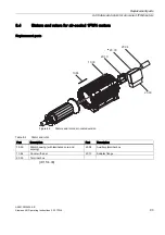
Страница 94: ...Stators and rotors for water cooled 1FW4 motors Replacement parts 10 00 20 60 20 00 20 04 20 11 Figure 8 1 Stator and rotor Table 8 1 Stator and rotor Part Description Part Description 10 00 Stator housing with laminated core and winding 20 11 Intermediate plate 20 00 Terminal box 20 60 Cable gland 20 04 Auxiliary terminal box ID 1132 00 ...

Страница 95: ...8 4 Stators and rotors for air cooled 1FW4 motors Replacement parts Figure 8 2 Stators and rotors air cooled version Table 8 2 Stator and rotor Part Description Part Description 10 00 Stator housing with laminated core and winding 20 04 Auxiliary terminal box 10 84 Cover with seal 20 10 Adapter flange 20 00 Terminal box ID 1133 00 ...

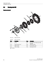
Страница 96: ...ush DE Replacement parts Figure 8 3 Bearing bush DE Table 8 3 Bearing bush DE Part Description Part Description 3 10 V ring 3 40 Deep groove ball bearing locating bearing 3 20 Outer bearing cover 3 50 Bearing housing 3 30 Retaining ring 3 61 Inner bearing cover 3 35 Grease slinger 5 00 Bearing shield DE ID 1134 00 ...

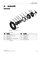
Страница 97: ...le 8 4 Bearing bush NDE Part Description Part Description 4 20 Outer bearing cover 4 61 Inner bearing cover 4 21 Outer bearing cover end cover 4 70 Insulating washer 4 30 Retaining ring 4 71 Insulating tube 4 35 Grease slinger 4 72 Insulating washer 4 41 Deep groove ball bearing floating bearing 4 73 Insulating ring 4 50 Bearing housing 6 00 Bearing shield NDE ID 1135 00 ...

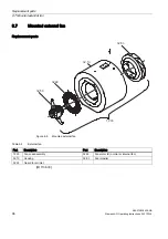
Страница 98: ...tructions 2 02 1FW4 8 7 Mounted external fan Replacement parts Figure 8 5 Mounted external fan Table 8 5 External fan Part Description Part Description 12 00 Fan cowl assembly 32 50 Fan motor IK normal or internal fan 32 10 Housing 32 53 Fan impeller 32 22 Guard for air inlet ID 1136 00 ...

Страница 99: ...g Instructions 2 02 1FW4 97 8 8 Pulse encoder Replacement parts Figure 8 6 Pulse encoder Table 8 6 Pulse encoder Part Description Part Description 55 10 Tachometer speed sensor 55 21 Adapter flange 55 32 Shaft journal with cone 55 63 Torque transmission element ID 1137 00 ...

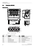
Страница 100: ...631 Part Description Part Description 20 20 Housing 20 70 Sealing insert for cable entry 20 30 Cover 20 86 Entry for auxiliary cable 20 38 Sealing cover 21 11 Connecting plate with internal cable 20 61 Cable gland upper part 21 41 Terminal supports 20 62 Cable gland lower part 21 61 Terminal strip for auxiliary circuit 20 65 Strain relief upper part 22 05 Terminal body 20 65 1 Socket head cap scre...

Страница 101: ...inal box 1XB1 631 A5E01083943A AB Siemens AG Operating Instructions 2 02 1FW4 99 Part Description Part Description 20 66 Strain relief lower part 22 43 Terminal link stepped 2 bores 20 66 1 Hexagon bolt DIN EN 24017 M8 ID 635 02 ...

Страница 102: ......

Страница 103: ...deration to the human ear s dependence on frequency a frequency weighting was introduced which simulates the limited sensitivity of the human ear for low frequencies 1000 Hz and high frequencies 5000 Hz This same frequency weighting is used throughout the world and is referred to as the A weighting DIN 45 633 All conventional sound measuring devices measure the sound pressure level dB and the A we...

Страница 104: ... second cooling circuit EN 60 034 6 1993 DIN VDE 0530 Part 6 1996 Degree of protection The degree of protection specifies both the suitability of electrical equipment for various ambient conditions and the level of protection against potential hazards to personnel who are using that equipment The protection type designation IP International Protection is followed by a 2 digit number The first numb...

Страница 105: ...able in straight or angled form with various threads for screwing them on DIN 71412 Grounding conductor The equipotential bonding wire is a wire that is used to connect conductive components to each other and to establish equalization of potential Insulation resistance Resistance of the insulation between two conductive components The insulating property of a material which isolates two adjacent c...

Страница 106: ...erating the stator s rotating field Strength class The characteristics of bolts and nuts are described with the aid of the strength classes This is done in accordance with EN ISO 898 1 based on 10 strength classes The characteristics such as tensile strength hardness stretch limit breaking elongation etc are listed in each case Temperature sensor Temperature sensor is a generic term for sensors th...

Страница 107: ...Glossary A5E01083943A AB Siemens AG Operating Instructions 2 02 1FW4 105 Work machine The driven machine is the element of the machine set that is driven by the motor via the shaft ...

Страница 108: ......

Страница 109: ...reaker 59 65 Cleaning 67 Cleaning with compressed air 72 Commissioning 65 Common mode filters 48 Compressor 36 Concentricity 33 Condensation water 34 40 68 Condensation water drain holes 40 Condensation water plug 68 Connecting terminals 56 connection 33 Connection 46 57 Connection cables 41 Control software 25 Converter output terminals 7 47 60 Converter pulse frequency 46 Coolant supply 34 Coola...

Страница 110: ... 43 Flow regulating valve 36 Forced cooling Housing 96 Foreign bodies in the cooling circuit 41 Foundation 76 Frequency converter 24 Frost danger 41 Full shaft rotor 23 Fusing the cable sections 59 G General inspection 73 Grease slinger 94 95 Grease types 73 Ground fault monitoring 49 Grounding clamp 49 Grounding connections 63 Grounding system Meshed 48 Guard for air inlet 96 I Inductance 31 Inse...

Страница 111: ... 48 Pulse encoder 97 Pulse frequency 64 Pulse inhibit 30 Pump 36 R Radial eccentricity 33 Radio frequency grounding 48 50 Rated current 27 28 30 Rated frequency 27 28 Rated power 27 28 Rated speed 27 28 29 30 Rated torque 27 28 29 37 Rated voltage 27 28 61 rating plate 26 27 91 Recooling unit 36 Regreasing 73 Regreasing device 33 Regreasing devices 42 Regreasing intervals 73 Retaining ring 94 95 R...

Страница 112: ...Maximum 29 31 Torque constant 31 32 Torque transmission element 97 Torque speed characteristic 29 Touch protection 41 59 63 67 Transport lock 41 Transporting 39 Type of balancing 42 Type of construction 26 27 28 33 Type of motor 27 28 32 V Vibration severity 33 Vibration speed 45 approved 33 Vibration free operation 45 Vibrations 46 Voltage 47 72 Voltage at the motor terminals 7 60 Voltage constan...

Страница 113: ......

Страница 114: ......

Страница 115: ......

Страница 116: ......

Отзывы: