background image

Features

6 - English

A26361-D1085-Z120-4-7419

I S A   1

I S A   3

I S A   2

P C I   2

P C I   1

P C I   3

P C I   4

3

2

1

1
2
3

4

5

6

7

8
9

1 0

1 1
1 2

1 3

1 4

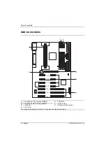
1 =   System fan
2 =   Chipcard reader
3 =   Power supply
4 =   Infrared receiver (IrDA)
5 =   Device ID
6 =   Power supply monitor
7 =   IDE drives 3 and 4 (secondary)

8 =   IDE drives 1 and 2 (primary)
9 =   Floppy disk drive
10 =  Processor fan
11 =  Control panel
12 =  Intrusion plug
13 =  Power On
14 =  Wake-up on LAN

The connectors marked do not have to be present on the system board.

Содержание D1085

Страница 1: ...nal conventions The meanings of the symbols and fonts used in this manual are as follows Pay particular attention to texts marked with this symbol Failure to observe this warning endangers your life destroys the system or may lead to loss of data i This symbol is followed by supplementary information remarks and tips Texts which follow this symbol describe activities that must be performed in the ...

Страница 2: ...identical battery or a battery type recommended by the manufacturer CR2032 Do not throw lithium batteries into the trashcan It must be disposed of in accordance with local regulations concerning special waste The shipped version of this board complies with the requirements of the EEC directive 89 336 EEC Electromagnetic compatibility Compliance was tested in a typical PC configuration When install...

Страница 3: ...bserve the following points under all circumstances You must always discharge yourself e g by touching a grounded object before working The equipment and tools you use must be free of static charges Pull out the power plug before inserting or pulling out boards containing ESDs Always hold boards with ESDs by their edges Never touch pins or conductors on boards fitted with ESDs ...

Страница 4: ...bytes main memory SDRAM Error identification and error recognition via ECC Flash BIOS AGP slot for AGP graphics controller AGP Accelerated Graphics Port 4 PCI slots all with busmaster capability 3 ISA slots IDE hard disk controller connected to PCI bus for up to four IDE drives e g IDE hard disk drives ATAPI CD ROM drive ultra DMA33 mode capable Real time clock calendar with integrated battery bac...

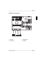
Страница 5: ...5 Z120 4 7419 English 5 Interfaces and connectors I S A 1 I S A 3 I S A 2 P C I 2 P C I 1 P C I 3 P C I 4 3 2 1 2 3 4 5 6 1 1 Serial port 2 2 Serial port 1 3 PS 2 mouse port 4 PS 2 keyboard port 5 Parallel port 6 USB ports ...

Страница 6: ... 1 4 1 System fan 2 Chipcard reader 3 Power supply 4 Infrared receiver IrDA 5 Device ID 6 Power supply monitor 7 IDE drives 3 and 4 secondary 8 IDE drives 1 and 2 primary 9 Floppy disk drive 10 Processor fan 11 Control panel 12 Intrusion plug 13 Power On 14 Wake up on LAN The connectors marked do not have to be present on the system board ...

Страница 7: ...troller IRQ12 Numeric processor IRQ13 IDE controller 1 IRQ14 01F0 01F7 IDE controller 2 IRQ15 0170 0177 assigned IRQ interrupts assigned as shipped Possible IRQ these interrupts can be used for your particular application Possible address this address can be used for your particular application Possible DMA these DMAs can be used for your particular application PCI bus interrupts The following tab...

Страница 8: ...tings with switch block I S A 1 I S A 3 I S A 2 P C I 2 P C I 1 P C I 3 P C I 4 3 2 1 O P E N O F F O N 1 2 3 4 5 6 7 8 Switch 1 must be set to off Switch 2 System BIOS recovery Switch 3 Write protection for floppy disks Switch 4 reserved Switches 5 8 clock frequency ...

Страница 9: ...he floppy disk drive To write and delete floppy disks the write protection in BIOS setup must be disabled in menu Security the field Diskette Write must be set to Enabled on The floppy disk drive is write protected off Read write and delete floppy disks is possible default setting Clock speed switch 5 6 7 and 8 The switches may only be set as specified in the table below for the particular process...

Страница 10: ...I S A 2 P C I 2 P C I 1 P C I 3 P C I 4 3 2 1 1 2 3 4 5 7 6 1 2 locations for main memory DIMM 2 1 location for main memory DIMM 3 1 AGP slot 4 4 PCI slots 5 3 ISA slots 6 Lithium battery 7 Pentium II with heat sink The connectors marked do not have to be present on the system board ...

Страница 11: ... memory modules are possible on request Then the board supports a maximum of 768 Mbytes DIMM Dual Inline Memory Module SDRAM Synchronous Dynamic Random Access Memory You may only use unbuffered 3 3V memory modules Buffered memory modules are not permitted SDRAM memory modules must have a cycle time of 15 ns or less or be designed for a clock frequency of 66 MHz or higher Installing memory modules ...

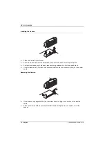
Страница 12: ...Add on modules 12 English A26361 D1085 Z120 4 7419 Removing a memory module 1 1 Flip the holders to the right and left of the location outwards 1 Pull the memory module out of its location 2 ...

Страница 13: ...o the left and right snap into place Set the clock frequency of the new Pentium II using switches 5 to 8 of the switch block If the Pentium II has a fan attach the associated cable to the fan connector FAN on the system board Removing the Pentium II If the Pentium II is equipped with a fan then disconnect the plug in connection of the related cable Press the clamps 2 on either side of the Pentium ...

Страница 14: ...the clock frequency of the new processor using switches 5 to 8 of the switch block If the Celeron has a fan attach the associated cable to the fan connector FAN on the system board Removing the Celeron 2 1 1 If the Celeron is equipped with a fan then disconnect the plug in connection of the related cable Press the two side holders somewhat outward while pulling the Celeron upward out of the socket...

Страница 15: ... a battery type recommended by the manufacturer CR2032 Do not throw lithium batteries into the trashcan It must be disposed of in accordance with local regulations concerning special waste Make sure that you insert the battery the right way round The plus pole must be on the top 1 2 3 Lift the contact 1 a few millimeters and remove the battery from its socket 2 Insert a new lithium battery of the ...

Страница 16: ......

Страница 17: ...ces and connectors 5 Resource table 7 PCI bus interrupts 7 Settings with switch block 8 Recovering System BIOS switch 2 9 Write protection for floppy disks switch 3 9 Clock speed switch 5 6 7 and 8 9 Add on modules 10 Upgrading main memory 11 Installing removing the processor 13 Replacing the lithium battery 15 ...

Страница 18: ...f International Business Machines Inc All other trademarks referenced are trademarks or registered trademarks of their respective owners whose protected rights are acknowledged Copyright Siemens AG 1999 All rights including rights of translation reproduction by printing copying or similar methods even of parts are reserved Offenders will be liable for damages All rights including rights created by...

Отзывы: