Содержание ME-3

Страница 1: ... K L SIEMENS ALLIS INSTRUCTIONS LOW VOLTAGE METAL ENCLOSED SWITCHGEAR TYPE ME AND OME 600 VOLTS J 18X1315 04 October 1975 Courtesy of NationalSwitchgear com ...

Страница 2: ... A Courtesy of NationalSwitchgear com ...

Страница 3: ...g Sections Plumb Line Instructions Leveling Indoor Switchgear Traveling Crane Installation Leveling Outdoor Switchgear Electrical Connections Bus Bars Transformer Bus Joints Typical Cable Lug Mounting Primary Cable Connections Secondary Control Wiring Ground Connection Current Transformer 6 24 6 24 6 24 7 24 7 8 MAINTENANCE General Inspections Lubrication General Electrical Contacts Corrosive Atmo...

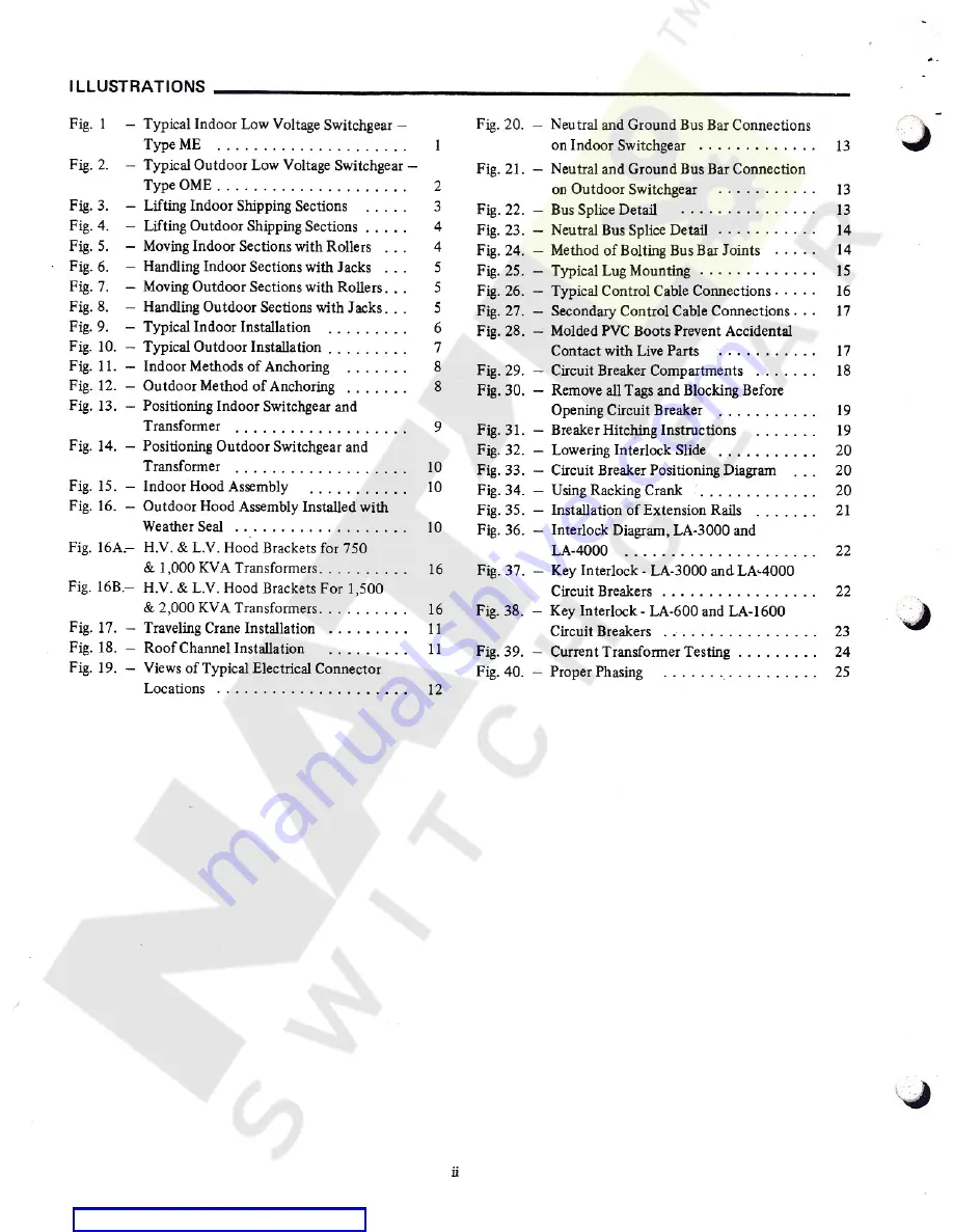
Страница 4: ...ting Fig 40 Proper Phasing Fig 1 Typical Indoor Low Voltage Switchgear Type ME Typical Outdoor Low Voltage Switchgear Type OME Lifting Indoor Shipping Sections Lifting Outdoor Shipping Sections Moving Indoor Sections with Rollers Handling Indoor Sections with Jacks Moving Outdoor Sections with Rollers Handling Outdoor Sections with Jacks Typical Indoor Installation 13 1 Fig 2 2 13 Fig 3 Fig 4 Fig ...

Страница 5: ...noted otherwise Allis Chalmers low voltage switchgear carries letter designations as follows ME for indoor and OME for outdoor equipment These designations may appear on drawings and other media and familarity with them will simplify communica tion with the factory Figures 1 and 2 show some typical installations Standard construction details of necessary auxiliary and accessory equipment are inclu...

Страница 6: ...he shelter for access to primary entrance compartments Indoor switchgear consists of one or more cubicles secured together as a single group It is completely operational when installed and connected to the customer s power and equipment Each cubicle consists of three or four stacked compartments framed and secured together as a single unit Circuit breaker compartments are provided with hinged acce...

Страница 7: ...tton to prevent accidental tripping during shipment See Figure 30 Identification In the case of multiple sections of load center substations the low voltage circuit breakers are key interlocked with the transformer primary switches Check substation numbers on the packaging of the switchgear and primary switches with those noted on the applicable General Arrangement and Floor Plan drawings These nu...

Страница 8: ...in place during moving and until final location is reached Jacking angles are provided on either side of indoor shipping sections Four angles are furnished for attaching to the corners of outdoor shipping sections Indoor jacking angles are removed and discarded when final location is reached Outdoor jacking angles may be removed when the jacks are no longer required Lifting channels are mounted on...

Страница 9: ...ximately 500 watts output within each cubicle to prevent condensa tion Space heaters are not standard equipment on indoor switchgear Oil or grease any moving parts such as hinges steel gears or drive screws if subjected to prolonged storage When batteries are supplied connect them to a charger Outdoor Switchgear When storing outdoor switchgear in an area exposed to the weather or humid conditions ...

Страница 10: ... are used the diameter of these pilings is to be determined by the customer for proper loading However they must not be less than twelve 12 inches for sufficient contact with base allowing for space for shipping split and space for grouting in of bed plate if used All shipping splits must be supported and taken into consideration when founda tion is constructed Foundation Extreme care should be ta...

Страница 11: ... shipping sections The General Arrangement drawing will indicate the shipping sections and their location within the line up Sections are assembled and wired in accordance with the arrangement as in final installation As previously covered under Foundation mounting surfaces sills slab piers or piling must be level and in the same plane Also conduits must be properly located and perpendicular to su...

Страница 12: ...ngement drawing with the side one inch from the edge of the transformer cover The flexible connectors are bolted to transformer terminals see General Arrangement drawing and a hood is bolted to the side of the switchgear and the top of the transformer tank Setting Shipping Sections After checking each shipping section for its proper location sequence as shown on the General Arrangement drawing mov...

Страница 13: ... Figure 13 Positioning Indoor Switchgear and Transformer 9 Courtesy of NationalSwitchgear com ...

Страница 14: ...ERFERENCE WITH THE SLINGS THE L V PLATE EXTENSION WILL BE IN THE PROPER POSITION WHEN SMIPPEO THE TRANSFORMER SHOULD BE LOCATED WITH THE L V LINE BUSHING 5 10 3 4 FROM FACE OF SWITCHGEAR OF L V BUSHING r FACE OF SWITCHGEAR 10 CAPTIVE NUTS SUPPLIED WITH TRANSFORMER S3 1 g a HOOD ANGLE BRACKETS STRAPPED TO RAO FOR SHIPPING Figure 16A H V L V Hood Brackets for 750 1000 KVA Transformers Figure 15 Indo...

Страница 15: ...door Switchgear With the first section of cubicles in place and lifting channels still rigidly attached examine each cubicle through anchor bolt holes to be certain that each point of anchor is in firm contact with sill channel or floor If there is no contact shims must be added adjacent to the anchor bolt holes These shims will prevent distortion of the section when anchor hardware is drawn tight...

Страница 16: ... HINGED BREAKER PANEL o V o o JC 192 92 0 9 r 9 93 K ID GROUND BAR CONNECTORS x BAR CONNECTORS I f l 4 LOCATION OF TERMINAL BLOCKS ON LM SIOE Of UNIT WHEN REQUIRED L C0 CT0 R3 LOCATION Of TERMINAL BLOCKS ON L H SIDE OF UNIT WKN REQUIRED LOCATION OF TERMINAL BLOCKS ON L H SIDE OF UNIT WHEN REQUIRED TO END OF TO ENQ OF BRKR STUO TO END OF BRKR STUO H 26 26 BRKR STUD INCOMING POWER CABLE CONNECTION M...

Страница 17: ... BAR rfTi rffa a 0i HU ITTT INSULATOR rm j 02 a 03 NOTE PLAN VIEW All hardware furnished is plated high strength steel Cap screws are 1 2 13 SAE Grade 5 Hex nuts are SAE Grade 2 except for LA 4000A bus bar joints 1 2 13 silicon bronze cap screws and nuts are furnished Figure 22 Bus Splice Detail exception to this arrangement occurs when aluminum bus is used In this case one Belleville spring washe...

Страница 18: ...ished for wiring between the switchgear auxiliary component and the temperature control system box on the transformer This conduit is to be installed and wired by the customer in the field CAP SCREW FLAT WASHERS 7 LOCK WASHER SILVER PLATED COPPER NUT FLAT WASHER CAP SCREW T On liquid transformer installations the conduit is furnished with the transformer for connecting to the switchgear in the fie...

Страница 19: ... CABLE LUG PER PHASE oo o oo o oo BOLTING ARRANGEMENT SAME AS DETAIL A DETAIL C ONE SINGLE 8 ONE DOUBLE LUG PER PHASE C 1 w oo oo oo raor oo oo oo r v C3 I MIN MIN BOLTING ARRANGEMENT SAME AS DETAIL V DETAIL D TWO DOUBLE LUGS PER PHASE O O o o o o cfa r i I 1 f LT u WD O O O O DETAIL E TWO DOUBLE LUGS UP TO 500 MCM 8 ONE SINGLE LUG UP TO 500 MCM PER PHASE ME 5 BOLTING ARRANGEMENT SAME AS DETAILS F...

Страница 20: ...pection and replacement see figure 29 In some applications they must be located in the bus com partment Current transformers for static trip device use are called tripping transformers They have a one ampere secon dary and are not suitable for metering They are mounted on the circuit breaker except when a ground fault trip element is furnished for a four wire application In this case a fourth trip...

Страница 21: ... crane or other suitable means for lifting the circuit breaker for insertion or removal CAUTION Make certain that the hoist is properly lubricated before using as outlined under Maintenance Page 26 Circuit Breaker Insertion LA 600 LA 1600 LA 600F or LA 1600F Place the circuit breaker in front of the cubicle and attach the lifting yoke furnished with accessories to the lifting holes provided on the...

Страница 22: ... racking crank and then raising interlock slide trip rod returns to its extended position per mitting trip shaft to reset and the breaker may be operated Between TEST and CONNECTED positions an interlock cam 11 figure 29 mounted on the com partment floor raises the interlock in the breaker The trip rod and trip shaft are held in the TRIP FREE posi tion so the breaker cannot be closed even if the i...

Страница 23: ...ompartment doors closed however for maintenance purposes position indicating labels are placed on the left hand compart ment rail to show breaker TEST and CONNECTED positions With the door closed breaker position is indicated by white lines on breaker cover using door iris as the indicator See figure 34 CLIP ANGLE HOIST EYE NUT HOIST 4 The procedure is the same for withdrawing the breaker from the...

Страница 24: ...st the fixed stops on the floor of the compartment 2 Move slide near top of sheet metal cover to the right exposing the square end of the screw 3 With racking crank furnished with accessories rotate the screw to position the cranks approximately as shown in View A figure 36 Move the breaker along the rail extensions until the cranks engage the fixed pins 10 figure 29 and 3 figure 35 mounted on the...

Страница 25: ...tton to its lower position 7 When the control toggle switch is in the ON position and the breaker is in TEST or CONNECTED position the stored energy springs will be automatically charged if the control circuit is energized 8 After the breaker is installed in the compartment remove extension rails 5 To move the breaker out of any position the previously described release procedure of raising the in...

Страница 26: ... AS SHOWN AND HOLD BREAKER TRIP FREE TURN AND REMOVE KEY BREAKER IS NOW LOCKED TRIP FREE TRIP SHAFT RED TRIP N BUTTON SPRING RETURN r I o KEY LOCK K r KEY HELD CAPTIVE I L _ i BREAKER INTERLOCK LATCH y o KEY INTERLOCK INTERLOCK BAR MTD ON COMPARTMENT FLOOR BAR SPRING RETURN SIDE VIEW SHOWING BREAKER INTERLOCK LATCH IN LATCHED IN POSITION PROCEDURE FOR RELEASING KEY LOCK INSERT KEY IN LOCK AND TURN...

Страница 27: ...nded lead at the current transformer and pass A measurable amount of current not to exceed five amperes through the lead to ground Pass suf ficient current to observe operation of relays and instru ments Manipulate the instrument switches and observe the phasing Repeat with each transformer Do this for metering and relaying current transformers only not tripping current transformers Inspection Che...

Страница 28: ...g the other two current trans formers of the remaining two phases The relay should then operate in the tripping position The directional control overcurrent element may have to be closed by hand if the current is insufficiently high to operate it In this test the trip circuit of the relay can be opened so as not to cause an outage CAUTION Certain control devices motors pushbuttons bell alarm conta...

Страница 29: ...ns Factors affecting inspection and maintenance scheduling are weather and atmosphere unusual number of operations experience of operating and maintenance personnel and special operating requirements Lubrication General It is essential that the switchgear be lubricated carefully and properly to guard against corrosion and to insure that all operating parts work freely A tube of electrical contact ...

Страница 30: ... of relays and instruments do not leave device covers off longer than necessary When a glass has been broken cover the device temporarily and replace broken glass as soon as possible Equipment Surfaces Matching paint is furnished with each order in spray on one pint cans one can per three cubicles This paint is thinned ready for touching up any scratches etc result ing from installation Inspect al...

Отзывы: