IV352 Rev.02
Date Issue:
2012-10-27
Page 149 di 232 + FR
be enabled. Press
႒
for over 5 seconds to confirm the setting.
4. In “Voltage lock-out” menu, press
"
or
!
to change the AC voltage where reactive power control will
be disabled. Press
႒
for over 5 seconds to confirm the setting.
5. In “Node 1 Power %” screen, press
"
or
!
to change the output active power (percentage of nominal
output power) for Node 1. Press
႒
for over 5 seconds to confirm the setting.
6. In “Node 1 PF” screen, press
"
or
!
to change the desired PF for Node 1. Press
႒
for over 5
seconds to confirm the setting.
7. Repeat step 5 and step 6 to complete the setting for Node 2~4.
8. “Set React. Power” message will be shown on the screen to indicate that the setting is saved.
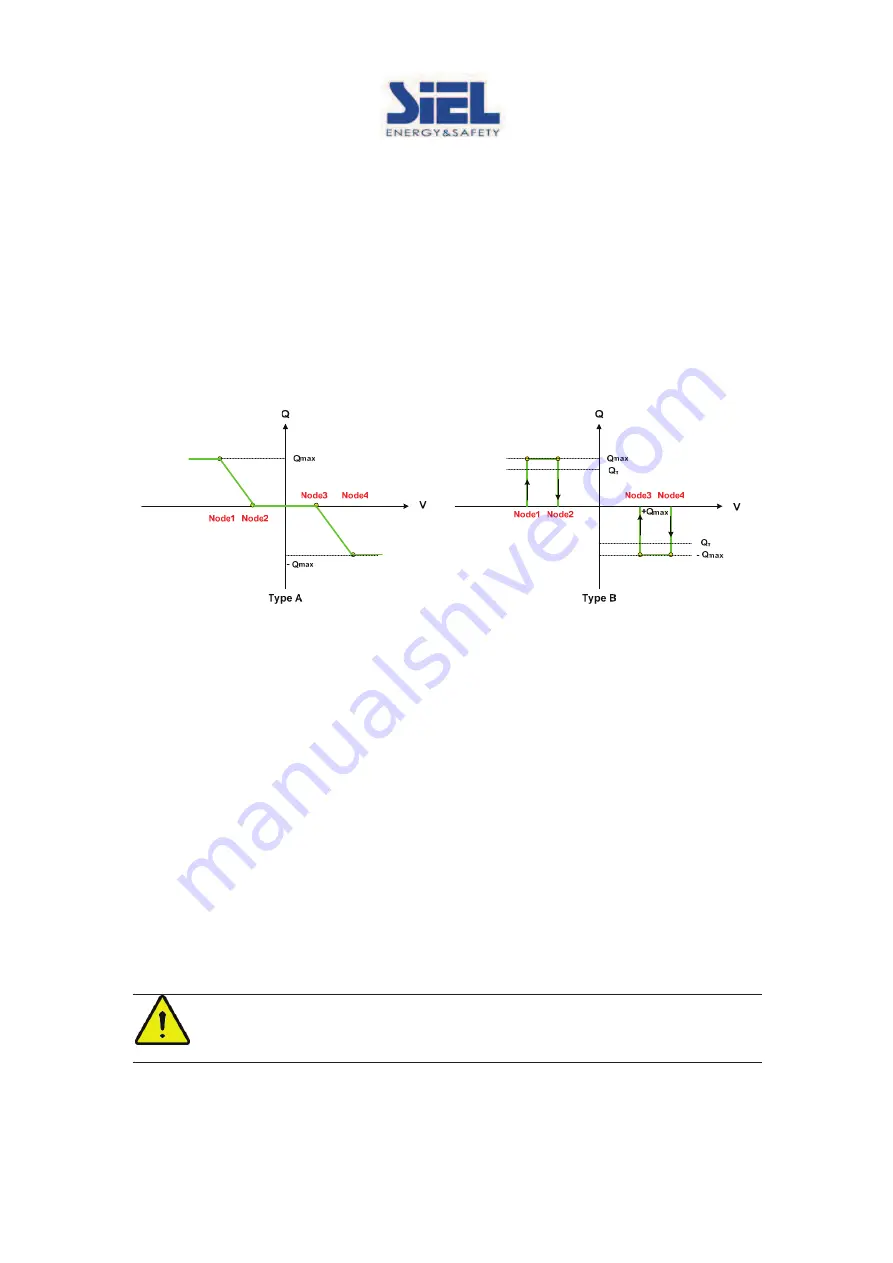
Curve Q(U)
In “Curve Q(U)” mode, user may let the reactive power (“Q”) change as the function of AC output voltage,
under given range of output active power. The relationship between Q and U may be specified by setting
Node 1~4 as shown in the example below.
1. Scroll to <Curve Q(U)> mode.
2. Press
႒
for over 5 seconds to set the type of Curve Q(U).
3. In “Type selection” screen, press
"
or
!
to change to the desired type. Press
႒
for over 5 seconds to
confirm the setting and go the next menu to set the output active power range in which the Curve Q(U)
mode will be activated.
4. In “Power lock-in” menu, press
"
or
!
to change the output active power (percentage of nominal
output power) where the reactive power control will be enabled. Press
႒
for over 5 seconds to confirm
the setting.
5. In “Power lock-out” menu, press
"
or
!
to change the output active power (percentage of nominal
output power) where the reactive power control will be disabled. Press
႒
for over 5 seconds to
confirm the setting.
6. In “Node 1 Volt. %” screen, press
"
or
!
to change the AC voltage (percentage of nominal AC
voltage) for Node 1. Press
႒
for over 5 seconds to confirm the setting.
7. In “Node 1 Q/S %” screen, press
"
or
!
to change the desired output reactive power (percentage of
output apparent power) for Node 1. Press
႒
for over 5 seconds to confirm the setting.
8. Repeat step 6 and step 7 to complete the setting for Node 2~4.
9. “Set React. Power” message will be shown on the screen to indicate that the setting is saved.
Warning:
The setting of reactive power control will affect the output power of inverter and therefore
shall only be set by qualified technician. Please contact your dealer to obtain the password if
needed.
Содержание SOLEIL 1F-TL2K
Страница 11: ...IV352 Rev 02 Data di emissione 2012 10 27 Pagina 11 di 232 FR SOLEIL 1F TL2K SOLEIL 1F TL3K SOLEIL 1F TL4K ...
Страница 77: ...IV352 Rev 02 Data di emissione 2012 10 27 Pagina 77 di 232 FR ...
Страница 87: ...IV352 Rev 02 Date Issue 2012 10 27 Page 87 di 232 FR SOLEIL 1F TL2K SOLEIL 1F TL3K SOLEIL 1F TL4K ...
Страница 109: ...IV352 Rev 02 Date Issue 2012 10 27 Page 109 di 232 FR Menu First Level Second Level Ⴃ Figure 3 2 1 Display Sequence ...
Страница 144: ...IV352 Rev 02 Date Issue 2012 10 27 Page 144 di 232 FR ...
Страница 153: ...IV352 Rev 02 Date Issue 2012 10 27 Page 153 di 232 FR ...
Страница 164: ...IV352 Rev 02 Ausstellungsdatum 2012 10 27 Seite 164 von 232 FR SOLEIL 1F TL2K SOLEIL 1F TL3K SOLEIL 1F TL4K ...
Страница 186: ...IV352 Rev 02 Ausstellungsdatum 2012 10 27 Seite 186 von 232 FR Menü 1 Ebene 2 Ebene Abbildung 3 2 1 Display Sequenz ...
Страница 231: ...IV352 Rev 02 Ausstellungsdatum 2012 10 27 Seite 231 von 232 FR ...


