background image

02.2019

34/44

H39.MFVRS006EN-00

Multi-point locks, key operated

Assembly instructions

BS 2100, BS 2800

4.13 

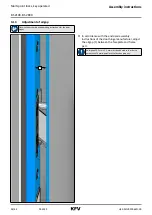
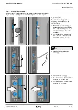
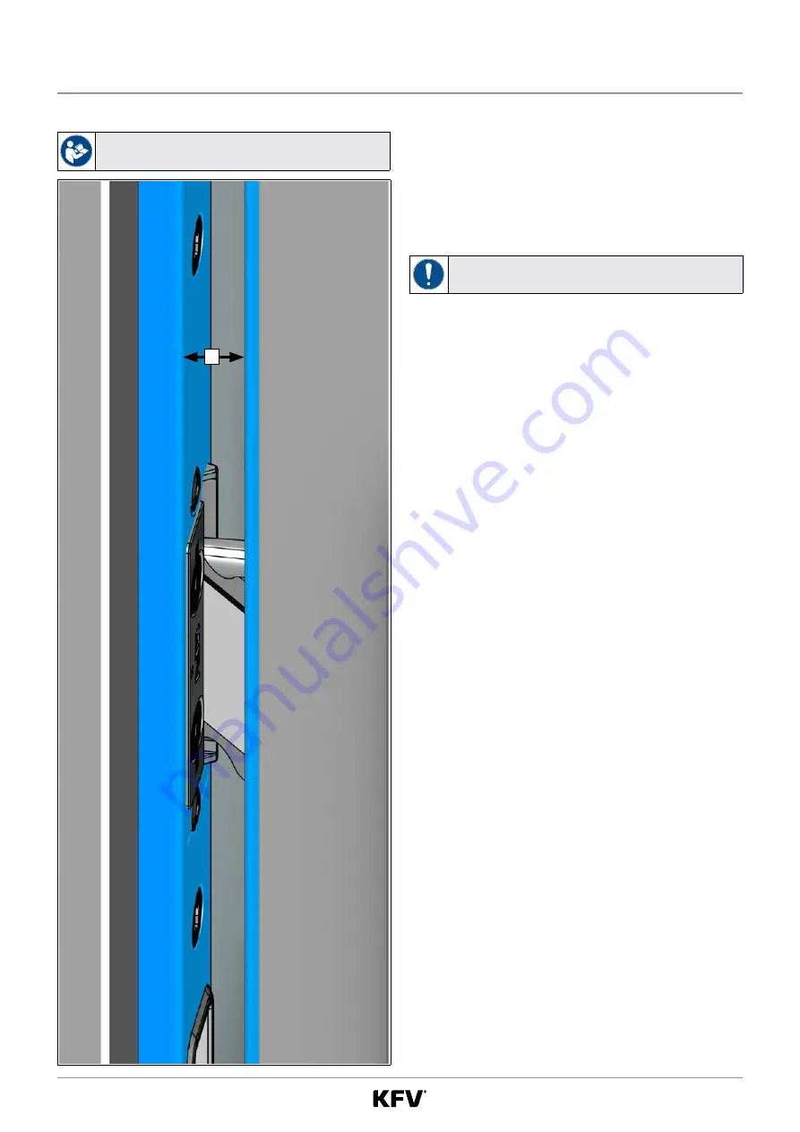
Adjustment of airgap

Observe the assembly and operating instructions for the door 

hinges.

1


f

In accordance with the enclosed assembly 

instructions of the door hinge manufacturer, adjust 

the airgap [1] between the faceplate and frame 

part.

An airgap of 3.5 mm ± 1.5 mm must be adhered to in order to 

permit the KFV multi-point locks to function properly.

Содержание KFV BS 2100

Страница 1: ...ASSEMBLY INSTRUCTIONS KFV BS 2100 BS 2800 Extension pieces A 2100 A 2800 Multi point locks Key operated Comfort systems Door systems Window systems...

Страница 2: ...02 2019 2 44 H39 MFVRS006EN 00 Multi point locks key operated Assembly instructions BS 2100 BS 2800...

Страница 3: ...h with swing door roller latch 16 4 2 2 Adjustment of swing door roller latch 17 4 3 Milling the door leaf 18 4 4 Installing the multi point lock 19 4 5 Extension pieces A 2100 A 2800 20 4 5 1 Croppin...

Страница 4: ...wet rooms or rooms in which the air contains aggressive or corrosive components Foreign objects and or materials which impede or prevent proper use must not be placed within the opening range the lock...

Страница 5: ...sitive components and must therefore be handled with care For example they must not be thrown hit hard or bent Do not carry the door by the lever handle or hardware when transporting it 1 7 Dimensions...

Страница 6: ...al site 1 13 Causes of damage Do not drill through the door leaf in the area of the gear box when the lock or the multi point lock is installed The spindle must not be hit through the lock nut with fo...

Страница 7: ...e door is open Force must be exerted on the lever handle only in the normal direction of rotation A maximum force of 150 N may be applied to the lever handle in the direction of actuation The lock or...

Страница 8: ...rsonal protective equipment You will need the following protective equipment when assembling multi point service locks Safety shoes Protective gloves Protective goggles 2 2 Heavy components When worki...

Страница 9: ...2100 BS 2800 3 Variants and components Two variants of the multi point lock are available with comfort mushroom cam 1 or with roller bolt 2 An extension piece 3 or 4 with an additional locking elemen...

Страница 10: ...763 737 403 1050 267 534 226 R005 2170 880 730 410 1049 260 310 110 R014 2170 770 730 410 1020 260 340 189 R016 2170 970 910 410 1042 260 138 R023 2170 970 910 410 1049 260 131 R024 2170 770 810 410 1...

Страница 11: ...267 310 110 R014 2170 763 730 403 1013 267 340 189 R016 2170 963 910 403 1035 267 138 R023 2170 963 910 403 1042 267 131 R024 2170 763 810 403 1035 267 238 212 R025 2170 763 810 403 1043 267 230 220 K...

Страница 12: ...264 310 110 R014 2170 766 734 406 1016 264 340 189 R016 2170 966 914 406 1038 264 138 R023 2170 966 914 406 1045 264 131 R024 2170 766 814 406 1038 264 238 212 R025 2170 766 814 406 1046 264 230 220 K...

Страница 13: ...19 5 31 5 54 12 H PZ 85 40 80 17 5 20 36 50 5 19 5 31 5 54 12 H PZ 88 35 17 5 16 33 53 5 16 5 31 5 51 12 H PZ 88 40 80 17 5 20 33 53 5 16 5 31 5 51 12 H PZ 92 25 17 5 without deadbolt 29 57 5 12 5 31...

Страница 14: ...02 2019 14 44 H39 MFVRS006EN 00 Multi point locks key operated Assembly instructions BS 2100 BS 2800 3 1 5 Additional locking elements BS 2100 9 4 7 3 7 8 11 19 19 11 5 9 4 19 19 BS 2300 19 8 11...

Страница 15: ...latch shank through the opening using the slotted screwdriver The latch shank will be released f f Remove the latch and rotate it by 180 CLICK f f Carefully press the latch into the gear box until th...

Страница 16: ...slotted screwdriver The latch shank will be released f f Remove the latch and replace it with the swing door roller latch CLICK f f Carefully press the swing door roller latch into the gear box until...

Страница 17: ...n wrench into the latch shaft through the hole in the centre part max 11 9 mm min 3 4 mm The swing door roller latch may only be unscrewed to the defined maximum value The position of the swing door r...

Страница 18: ...from page 10 Wear safety goggles 1 2 5 E 3 4 Routed pocket for the main lock 1 16 0 mm 2 234 0 mm 3 137 0 mm 4 17 5 mm 1 mm 5 Backset E PZ dimension With 94 mm PZ dimension the rear backset item 4 is...

Страница 19: ...tions Multi point locks key operated BS 2100 BS 2800 4 4 Installing the multi point lock 1 f f Insert the multi point lock in the milled door leaf f f Adjust the multi point lock to the handle nut 1 1...

Страница 20: ...e multi point lock can be supplemented at the top with an extension piece with a further locking element A 2100 A 2800 Min 10 mm 195 7 mm 185 7 mm Max K rzbarkeit 298 6 mm 298 6 mm Min 10 mm 195 7 mm...

Страница 21: ...locks key operated BS 2100 BS 2800 4 5 1 Cropping the multi point lock 1 2 25 mm 2 f f On the faceplate on the multi point lock 1 measure 25 mm upwards from the middle of the fastening hole 2 above t...

Страница 22: ...6EN 00 Multi point locks key operated Assembly instructions BS 2100 BS 2800 4 5 2 Inserting the multi point lock 1 f f Insert the multi point lock in the milled door leaf f f Adjust the multi point lo...

Страница 23: ...N 00 02 2019 23 44 Assembly instructions Multi point locks key operated BS 2100 BS 2800 f f Leave the top four screwing points free f f Screw the multi point lock to the door leaf at the remaining scr...

Страница 24: ...structions BS 2100 BS 2800 4 6 Measure and crop the extension piece The faceplate and drive rod must not be bent f f Carefully draw the faceplate forwards 1 2 f f Guide the cam 1 of the drive rod of t...

Страница 25: ...up to max 10 mm over the middle of the fastening hole 1 f f Insert the multi point lock together with the extension piece into the door leaf f f Mark the cropping position on the extension piece 1 2 3...

Страница 26: ...y instructions BS 2100 BS 2800 4 7 Installing the multi point lock and extension piece f f Connect the extension piece to the multi point lock once again f f Insert the multi point lock together with...

Страница 27: ...lling see chapter 3 1 4 Main lock types key operated from page 13 Dismount the multi point lock before drilling Marking and drilling the holes f f With the multi point lock installed adjust the drilli...

Страница 28: ...EN 00 Multi point locks key operated Assembly instructions BS 2100 BS 2800 f f Fix the cylinder lock with the cylinder lock screw 1 f f Install the handle set according to the enclosed assembly instru...

Страница 29: ...mensions given refer to E8H frame part Main lock Contact the KFV customer service to find out the cutting dimensions for other frame parts or locking rails Q adjustment of the auxiliary boxes 1 21 0 m...

Страница 30: ...frame parts Maximum interval 5 mm Minimum interval 3 mm Maximum interval 5 mm The prescribed maximum interval between the bottom edge 1 of the comfort mushroom cam in the release position and the inle...

Страница 31: ...frame part for main lock into the routed pocket of the frame Use the prescribed screws for SKG certified frame parts see chapter 4 10 Requirements for SKG certification from page 30 Use the screws re...

Страница 32: ...m 298 6 mm Frame part for A 2100 The position of the cam on the extension piece measured from the bottom edge of the extension piece to middle of the cam is 298 6 mm f f Position the frame parts accor...

Страница 33: ...sition and the inlet edge 2 of the frame part must not exceed 5 mm This ensures that the roller bolt achieves the specified minimum dimension for the grip into the frame part An interval of min 3 mm m...

Страница 34: ...Observe the assembly and operating instructions for the door hinges 1 f f In accordance with the enclosed assembly instructions of the door hinge manufacturer adjust the airgap 1 between the faceplate...

Страница 35: ...r The latch must engage in the AT piece 1 and the door must remain locked If the latch does not engage or if the pressure on the door seal is too high the AT piece must be adjusted in the direction of...

Страница 36: ...door and check whether the latch engages properly Repeat the adjustments if necessary Day latch 1 T 10 The day latch differs from the AT piece by means of a sliding handle 1 releasable fitting part Th...

Страница 37: ...right up to 90 Adjustment in the direction of the door leaf increases the compression Adjustment in the direction of the frame reduces the compression Spanner allen key optionally available Material n...

Страница 38: ...ached when the marking is in a 90 position 4 mm f f Turn the roller bolts 1 to the left or right up to 90 Adjustment in the direction of the door leaf increases the compression Adjustment in the direc...

Страница 39: ...ndle f f Press the lever handle down fully Check the function of the lever handle and the latch f f Let go of the lever handle The lever handle must return to its original position by itself and the l...

Страница 40: ...f Press back the locking elements manually The locking elements must not move back in case of counter pressure 2X Releasing the locking elements f f Turn the key in the unlocking direction with a dou...

Страница 41: ...engage f f Adjust the AT piece in the direction of the door leaf If the latch has too much play f f Adjust the AT piece in the direction of the frame Check the release of the latch with the lever hand...

Страница 42: ...n The main lock bolt must extend completely and the cams must retract into the frame parts The door leaf must be moved laterally onto the seal 2X Retracting the locking elements f f Turn the key in th...

Страница 43: ...lock When the routed pocket is compliant with the specified dimensions and the sluggishness persists the multi point lock must be checked by KFV f f If the routed pocket does not comply with the spec...

Страница 44: ...www siegenia com H39 MFVRS006EN 00...

Отзывы: