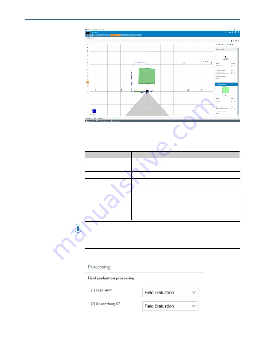
The
Edit field points
tool (mouse pointer in the list of tools to the left of the scan
view) can be used to customize the field geometry with the assistance of the
mouse pointer. Alternatively, the field vertices can also be customized by entering
the coordinate values in the
Field coordinates
mask.
Table 10: Options for editing the field geometry with the mouse pointer
Function
Procedure
Scale field
Drag square red handle.
Rotate field
Drag round black handle.
Customize field shape
Drag square green handle.
Add field vertices
Double-click in required position.
Remove field vertex
Click to select square green handle and press the
[del]
key.
Delete field
Press the
[del]
pushbutton without first selecting a green han‐
dle.
Insert new field (function
is only available if a field
has not been created)
Select
Insert field points
tool, click to set field vertices, and
double-click last field vertex to close the field.
NOTE
Fields are defined on the y global plane.
Depending on the mounting location of the device (specified in the Default view),
the fields are then projected onto the scan plane.
•
Processing
: Further input fields for field evaluation processing (e.g. minimum per‐
pendicular distance to reference line).
•
Interfaces
. Configuration of the interfaces (left-hand side) and input of communica‐
tion parameters (right-hand side).
7
OPERATION
42
O P E R A T I N G I N S T R U C T I O N S | LMS1104C-111031S01
8023051/1AZG/2021-05-10 | SICK
Subject to change without notice


