


Table 3: Correction factor for sensing ranges S
ao
, S
ar
and S
n
Material
Correction factor
Mu-metal
1.2
Molded metal
1.1
Structural steel (Fe 360)
1.0
Rust-free steel (V2A, 304)
0.8
Aluminum
0.45
Copper
0.3
Brass
0.4
Example calculation
For a copper actuating element, the safe switch-off distance changes as follows:
S
ao/copper
= S
ao
* 0.3
4.4
Integration in the electrical control
Switch-on commands that put the machine in a dangerous state may only be activated
when the safety switch detects an actuating element. When the machine goes into a
dangerous state, a stop command must be triggered if no suitable object is detected.
Depending on the safety concept, the signal is analyzed by safety relays or a safety con‐
troller, for example.
The connected control and all devices responsible for safety must comply with the
required performance level and the required category (for example, according to
EN ISO 13849-1:2015).
4.4.1
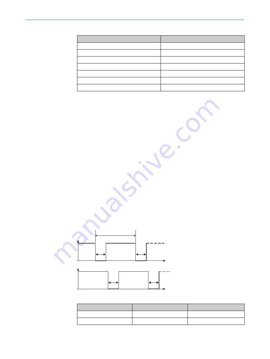
Course of the OSSD test over time
The safety locking device tests the OSSDs for self-diagnosis at regular intervals. To
do this, the safety locking device switches each OSSD briefly to the OFF state and
checks whether this channel is voltage-free during this time.
Make sure that the machine’s control does not react to these test pulses and the
machine does not switch off.
OSSD 1
V
t
1
2
V
t
2
OSSD 2
2
2
Figure 2: Course of the OSSD test over time
Legend number
Description
Value
1
Test pulse interval
Usually every 20 ms
2
Test pulse width
300 μs
PROJECT PLANNING
4
8023341/14TD/2019-08-08 | SICK
O P E R A T I N G I N S T R U C T I O N S | IME2S
13
Subject to change without notice