


OPERATING INSTRUCTIONS | DOSIC
®
8020955/11HD / 2018-12-12| SICK AG
Subject to change without notice
25
7
COMMISSIONING
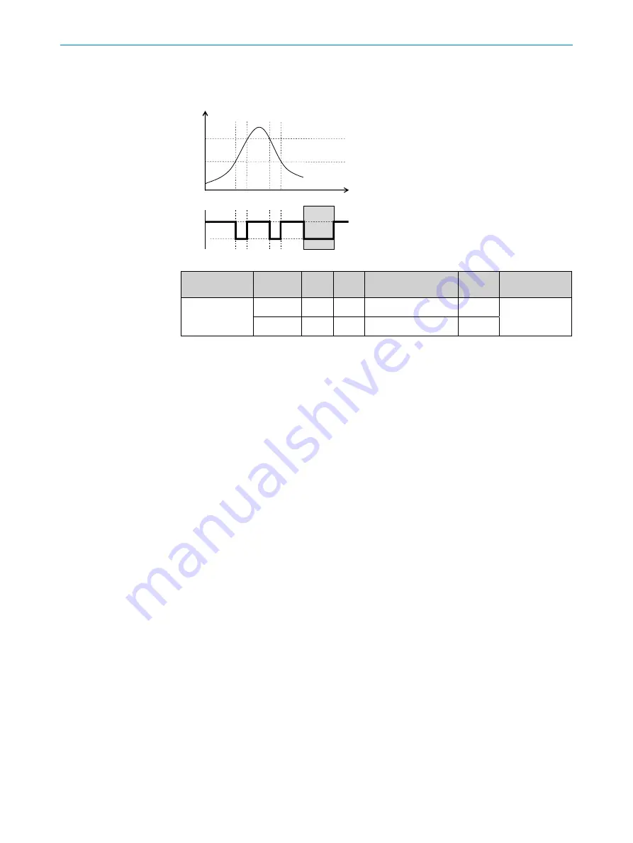
Switching output behavior
Flow/temperature
t
FH
FL
Error signal
active
deacti-
vated
Switching
output
PNP
NPN
DRV
OC
Error status
Normally
closed/FNC
Active
High
Low
High (PNP switched)
Low
Inactive
Inactive
Low
High
Low (NPN switched)
High
7.3.7
Pulse output
If pulse has been selected as output for Q2, PlsVal can be used to define the pulse
value (definition of the volume that generates a pulse). PlsWid can be used to define
the pulse width (duration of a pulse in μs).
Example:
PulsVal = 1000 ml, PulsWid = 50 μs
A pulse will be generated when 1000 ml are counted and the pulse duration will be 50
μs.
It is important to ensure that the pulse width set is as short as possible and as long as
necessary so that the device connected to the digital output still recognizes the pulse
(to avoid overlapped pulses). If the set pulse value is reached, a pulse is sent out at the
digital output.
If the pulse valency chosen by the user is too low, the pulse repetition rate can get too
high, leading to the sensor outputting a lower number of pulses than it should. If this is
the case, the sensor will show the warning [i]HiFrq on the display (and “Q2 frequency
too high” over the active notifications of IO-Link).
Example:
Configuration: PlsVal = 100 μL
Measured flowrate = 60 L/min --> Pulse repetition rate clipped to 100 ns -->
Warning [i]HiFrq
7.3.8
Frequency output
If frequency has been selected as the output for Q2, FrqMax and FrqMin can be used to
define the maximum and minimum frequencies.
The maximum frequency corresponds to the fullscale value. The minimum frequency
corresponds to the intial scale value.
The fullscale value and the initial scale value are defined by Q2SP and Q2RP respec
-
tively.