


C D F 6 0 0 - 2 2 0 0 | S I C K
8015922/1CC9/2021-07-12 • Subject to change without notice •
SICK AG
•
Waldkirch
•
Germany
•
www.sick.com
2
•
The device must only be mounted by inserting two screws
into the elongated drill holes.
•
Stable mounting equipment with sufficient load-bearing ca
-
pacity and appropriate dimensions for the fieldbus module.
The module has been optimized for mounting on standard
frame profiles. Weight 360 g (without cables).
Dimension drawing
•
Required switching space across the electrical connections:
approx. 300 mm, access to USB interface and rotary encod
-
ing switch: approx. 400 mm.
•
Clear view of the transparent panels on the rotary encod
-
ing switch and the optical indicators.
•
In order to achieve electromagnetic-compatible mounting,
a continuous metallic connection must be established with
the housing.
1.
Use the two elongated drill holes to mount the fieldbus
module in the lugs of the cover or the bar on the side. Ide
-
ally, the fieldbus module should be mounted in a horizontal
or vertical position, so that the writing on the rotary encod
-
ing switches reads correctly when viewed by the user.
2.
Mount the ID sensor and align it with the codes/transpon
-
ders to be identified as indicated in the corresponding
operating instructions. The
&
operating instructions of
the relevant ID sensor are available on the corresponding
product site online, e.g., for the CLV62x bar code scanner
at
www.sick.com/CLV62x.
Step 2: Electrical installation
•
Only skilled electricians with appropriate training
and qualifications are permitted to perform electrical
installation
.
•
Standard safety requirements must be met when working
in electrical systems!
•
Electrical connections between the fieldbus module and
other devices may only be made or separated when there
is no power to the system. Otherwise, the devices may be
damaged.
•
Where connecting cables with one end open are con
-
cerned, make sure that bare wire ends are not touching
(risk of short circuit when the supply voltage is switched
on). Wires must be appropriately insulated from each
other.
•
Wire cross sections of the supply cable from the cus
-
tomer's power system for the fieldbus module should be
designed and protected in accordance with the applicable
standards. Insert a separate, external fuse (max. 3 A slow-
blow) at the start of the supply cable to protect the fieldbus
module (and the ID sensor connected to it).
•
All electric circuits to be connected to the fieldbus module
must be designed as SELV circuits (SELV =
S
afety
E
xtra
L
ow
V
oltage).
a
DANGER
Risk of injury and damage caused by electrical current!
The CDF600-2200 fieldbus module is designed for opera
-
tion in a system with proficient grounding of all connected
devices and mounting surfaces to the same ground potential.
Incorrect grounding of the fieldbus module can result in
equipotential bonding currents between the fieldbus module
and other grounded devices in the system. This can lead to
hazardous voltages being applied to metal housing, cause
devices to malfunction or sustain irreparable damage and
damage the cable shield as a result of heat rise, causing
cables to set alight.
•
Only skilled electricians should be permitted to carry out
work on the electrical system.
•
Ensure that the ground potential is the same at all ground
-
ing points.
•
If the cable insulation is damaged, disconnect the power
supply immediately and have the damage repaired.
See
&
CDF600-22xx Fieldbus Module Technical Informa-
tion
(no. 8015924), available on the product site on the web
(
www.sick.com/CDF600-2)
for suggested courses of action
for eliminating hazards.
1.
In order to install the desired application, wire the fieldbus
module as appropriate for the ID sensor type with the help
of the optional pre-assembled SICK cables as shown in
the block diagram. The cables are only included as ac
-
cessories in the delivery of the module if they are ordered
separately. The part number varies by type for the required
M12 adapter cable to D-Sub HD ("DEVICE" connection)
for the ID sensor with Ethernet interface. It should, for ex
-
ample, be taken from the operating instructions or product
information for the ID sensor on the corresponding online
product page.
Cable types and lengths:
•
The cable used for the incoming supply cable must be
a screened cable, length of cable < 30 m.
Take appropriate measures to isolate unused open wire
ends (CAN bus) for the "POWER" connection (risk of
short-circuit)
•
Screened connection cable between fieldbus module
and ID sensor < 5 m, as a RS-232 interface to the data
transmission is used between fieldbus module and
ID sensor.
2.
Prepare and protect the supply voltage for the fieldbus
module. The level of the supply voltage for the unit consist
-
ing of fieldbus module and ID sensor is dependent on the
connected sensor, see
The fieldbus module provides a supply voltage range of
DC 10 V to 30 V. The supply voltage is also applied to the
connected ID sensor. The power supply and all connected
signals must comply with the regulations for extra-low volt
-
ages with safe separation (SELV) according to EN 61010.
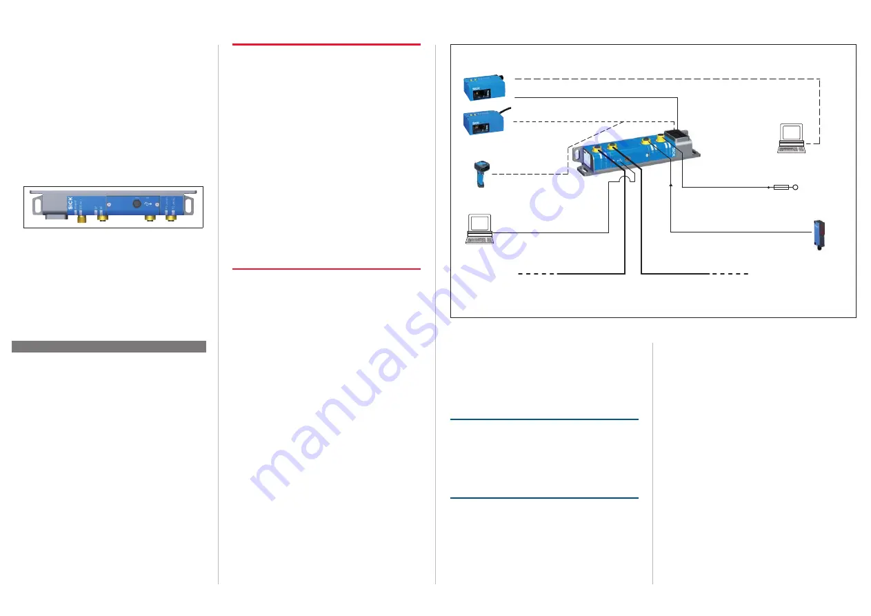
10 V ... 30 V DC
3)
(LPS/SELV)
Cable e. g. no. 6048241, 2 m
(2 x 4-pin M12 plug, D-coded)
Cable e. g. no. 6048241, 2 m
(2 x 4-pin M12 plug, D-coded)
SOPAS ET
Trigger IN (reading clock)
e. g. CLV63x bar code scanner
(Ethernet version, M12)
Trigger
sensor
Data (Aux, RS-232)
Supply voltage
Data (Aux, RS-232)
Supply voltage
PROFINET (data)
PROFINET (data)
Supply voltage/
(CAN
2)
, if required)
Cable e. g. no. 6036384, 5 m
(5-pin M12 socket, A-coded/
open end)
Cable e. g. no. 6026133, 2 m
(5-pin M12 plug, A-coded/open end)
Ethernet (cable e. g. no. 6034414, 2 m,
4-pin M12 plug, D-coded/8-pin RJ45 plug)
Alternative connection of ID sensor
(Ethernet version) for configuration/
diagnostics
ID sensor
(Standard version,
with cable)
– or –
– or –
“USB”
“POWER
”
“EXT. IN 1”
SOPAS ET
1) Characteristic of the sensor related cable end depends of ID sensor type
2) CAN network always terminated at one end with resistor in the fieldbus module
3) Depends on connected ID sensor type
Data (RS-232)
Supply voltage
IDM16x
Configuration/diagnostics of
proxy compatible ID sensors
Cable no. 2057709, 0.3 m +
cable e. g. no. 6041540, 1.8 m
External
fuse
“DEVICE”
CDF600-2200
Fieldbus module
Cable
1)
e. g. no. 2041834, 2 m
(12-pin M12 plug, A-coded/15-pin D-Sub HD plug)
USB cable e. g. no. 6036106, 2 m
(4-pin plug type A/5-pin plug type
micro B)
„P2 PROFINET
“
„P1 PROFINET
“
Block diagram: CDF600-2200 fieldbus module connected to CLV6xx bar code scanner or IDM 16x hand-held scanner (example)
Power output of the power source:
The fieldbus module itself consumes < 5 W power (without
ID sensor and trigger sensor).
The additional power consumed by the connected ID sensor
and trigger sensor (if there is one) varies by type.
The output of the power supply unit must be dimensioned
based on the total consumption of all loads.
NOTE
Risk of damage caused by electrical current!
The supply voltage at the DEVICE connection is not short-
circuit-protected. If the "POWER" LED no longer lights up
following a short-circuit between pin 1 and pin 5, the device
must be sent to SICK Service so that its functionality can be
re-established.
3.
Do
not
connect the supply voltage yet.