


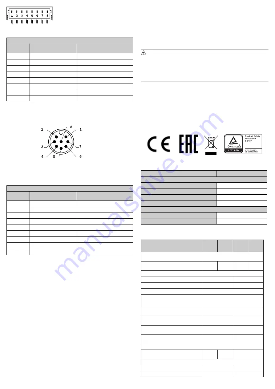
Figure 1: In-line plug connection, 8-pin
8-pin in-line plug pin assignment
PIN and wire allocation SKS36S/SKM36S
PIN
Signal
Cable color
(Cable outlet)
1
U
S
Red
2
+ SIN
White
3
REFSIN
Brown
4
+ COS
Pink
5
REFCOS
Black
6
GND
Blue
7
Data +
Gray or yellow
8
Data -
Green or violet
Version with round plug (Fig. 2/3)
b
Insert the cable socket while voltage-free and screw tight.
8-pin A-coded
View of plug side
Figure 2: Round plug connection, 8-pin
Pin assignments for round plug, 8-pin
SKS36S/SKM36S Stand-Alone pin and conductor assignments
PIN
Signal
Cable color
(Cable outlet)
1
REFSIN
Brown
2
+ SIN
White
3
REFCOS
Black
4
+ COS
Pink
5
Data +
Gray or yellow
6
Data -
Green or violet
7
GND
Blue
8
U
S
Red
Shield
5.2 Signals of the encoder system
The SKS36S/SKM36S safe motor feedback system has the following HIPER‐
FACE® interface signals:
•
V
S
– Supply voltage to the encoder. The operating voltage range of the
encoder is b 7 V and +12 V. The recommended supply voltage is +8
V.
•
GND - Encoder ground connection; electrically isolated from the housing. The
voltage relating to GND is + U
S
.
•
+ SIN – Process data channel; + SIN is a sine signal of 1 Vpp with a static
offset of REFSIN.
•
REFSIN – Process data channel; a +2.5 V static voltage which serves as the
reference voltage for +SIN.
•
+ COS – Process data channel; + COS is a cosine signal of 1 Vpp with a sta‐
tic offset of REFCOS.
•
REFCOS – Process data channel; a +2.5 V static voltage which serves as the
reference voltage for + COS.
•
Parameter channel; positive data signal. The parameter channel is an asyn‐
chronous, half-duplex interface, which physically conforms to the EIA RS485
specification. For this, data can be requested from the encoder through dif‐
ferent commands; this also makes it possible to write user-specific data
such as position offset to the EEPROM of the encoder
•
Parameter channel; negative data signal. The parameter channel is an asyn‐
chronous, half-duplex interface, which physically conforms to the EIA RS485
specification. For this, data can be requested from the encoder through dif‐
ferent commands; this also makes it possible to write user-specific data
such as position offset to the EEPROM of the encoder
6
Commissioning
To commission the safe motor feedback system, SKS36S/SKM36S, it is assumed
that the manufacturer of the connected drive system has complied with the safety
requirements for the drive system design, as described in the implementation
manual, "Hiperface Safety".
Further measures are not required for commissioning.
6.1 Inspection instructions
Further inspection measures are not required for commissioning and during oper‐
ation.
WARNING
Observe the mission time!
The SKS36S/SKM36S safe motor feedback systems have a specified maxi‐
mum mission time, after which they must always be taken out of service.
The bearing service life must be taken into account in addition to the mission
time. The parameter which is first reached depending on the application
determines the time when the system must be taken out of operation.
The year of manufacture of the motor feedback system is specified on the device
label and/or packaging label using a four digit code (yyww). The first two digits yy
specify the year (without the century), the last two digits ww specify the calendar
week of the last manufacturing process.
6.2 Declaration of conformity
The SKS36S/SKM36S safe motor feedback system family was manufactured in
accordance with the following directives:
•
the machinery directive 2006/42/EC
•
the EMC directive 2014/30/EU
The complete EU declaration of conformity is available at the SICK homepage on
the Internet: www.sick.com
7
Order data
Type
Item no.
SKS36S/SKM36S tapered shaft
SKS36S-HFA0-K02
1036556
SKM36S-HFA0-K02
1036558
SKS36S-HFA0-S01
1083415
SKM36S-HFA0-S01
1083412
SKS36S/SKM36S Stand-Alone
SKS36S-HVA0-K02
1036557
SKM36S-HVA0-K02
1036559
8
Technical data
SKS36S
Conical
Shaft
SKM36S
Conical
Shaft
SKS36S
Stand
Alone
SKM36S
Stand
Alone
Number of sine/cosine periods per revolu‐
tion
128
Number of absolutely encodable revolu‐
tions
1
4096
1
4096
Dimensions
see dimensional drawings
Weight
0.07 kg
0.14 kg
Rotor moment of inertia
4.5 gcm²
6 gcm²
Code type for the absolute value
binary
Code sequence when rotating the shaft
clockwise while looking towards "A" (see
fig. 3)
increasing
Measuring step for interpolation of the
sine/cosine signals with e.g. 12 bit
2.5 angular seconds
Error limits for evaluation of the 128 sig‐
nals, integral non-linearity
± 80 angular sec‐
onds
-
Non-linearity of a sine/cosine period, dif‐
ferential non-linearity
± 40 angular sec‐
onds
-
Error limits for evaluation of the 128 sig‐
nals, non-linearity
-
± 120 angular sec‐
onds
Output frequency for sine/cosine signals
0 … 65 kHz
Working speed
12000
min
-1
9000
min
-1
6000 min
-1
Max. angular acceleration
5 x 10⁵ rad/s²
Operating torque
0.2 Ncm
0.6 Ncm
Start-up torque
0.3 Ncm
0.9 Ncm
8014124/10RG/2018-08-20/de, en, es, fr, it
SKS36S/SKM36S, SKS36S Stand-Alone, SKM36S Stand-Alone | SICK
7