


33
Control 485 - with 3rd party (IR) via Fontus
CONTROL 485 WITH 3RD PARTY
(IR) via FONTUS
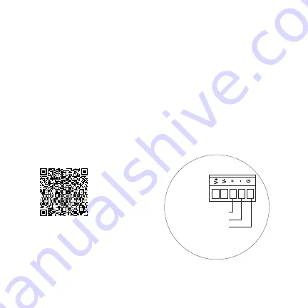
IR Input
NOTE: Refer to the drawings on pg 27-28. See below
for the IR Fontus pinout. For more details, refer to
pg 8 of the pdf in the included Fontus instructions.
Alternatively you can scan the QR code here to access
the instructions.
(Green) Data (+)
IR Receiver
Input
(Yellow) Data (-)
(Black) Ground


