background image


- 31 -

Operations


Track 

 
The Track function provides a record of the path over which your vessel has traveled. A track is a 
series of lines connecting points of vessel present position which are plotted at wither time or distance 
intervals. Tracks are recorded and stored one at a time. AQUA supports five different tracks, each has 
up to ten thousand (20,000) points of track history. Tracks are displayed on the Main Plotter Screen in 
any user selectable combination from none to five. Current track status is displayed on the lower line of 
the GPS area of the information display. Track number, on/off condition, and number of track points 
used are presented. 


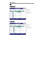
1. Track ON/OFF 

 [ENTER]->[1.Track]->[

][

]. For displaying on/off, use the arrow keys, right and left. 


2. Changing Track Color 

 [MENU]->[8.User Data Edit]->[2. Track Color]. For choosing the color you want, use the arrow keys, 

right and left. 
 

3. Deleting Track 

 [MENU]->[8.User Data Edit]->[3. Track Deletion]->Choose the color you want to delete  

->[ENTER]  
(* If you want to delete all tracks, choose “All Delete”) 
 

4. Changing Track page 

 Saving 10,000 points are available in each page. 

 [MENU]->[4.Setup 1/2]->[0.Track Pages]->[

][

 
5. Loading Track  

 Saving 10,000 points are available in each . 

 [MENU]->[4.Setup 1/2]->[enter]->[9.Load track]->[ENTER] 


User Data 


Save User Data(Back-up) 

 Insert the SD card 

-> [MENU] -> [1. Edit] -> [6. Save User Data] -> [ENTER] 

*SD card must be a normal type. (mini SD and Mirco SD are not available) Please, kindly note that the 
maximum is 2GB. 


Load User Data 

 Insert the SD card 

-> [Menu] -> [1. Edit] -> [7. Load User Data] -> [ENTER] 

*SD card must be a normal type. (mini SD and Mirco SD are not available) Please, kindly note that the 
maximum is 2GB.

Содержание GPS-95CP

Страница 1: ... Modes Display Modes 17 1 Full Chart Display 18 2 Plotter Display 20 3 Lat Lon Display 21 4 Highway Display 22 5 Steering Display 23 6 Nav data Display 24 Operations Edit 25 MOB 27 Mark 28 1 Creating Mark 2 Changing Mark symbol 3 Changing Mark color 4 Deleting Mark 5 Editing Mark WPT Waypoint 29 1 Creating destination point 2 Creating WPT 3 Selecting WPT 4 Editing WPT ...

Страница 2: ...n Off 2 Changing Track Color 3 Deleting Track 4 Change Track page 5 Loading Track User Data 31 Display On Off 32 Map Orientation 32 1 True motion 2 North up 3 Course up 4 Head up GPS Setup 1 2 33 1 Datum 2 Satellite Information 3 Latitude Modification 4 Longitude Modification 5 Smoothing set 6 Average COG 7 Average SOG 8 Lat Lon Unit 9 GPS Receiving Port 0 Coordinate System ...

Страница 3: ...odification 0 TD Setup Setup 2 2 35 1 Displaying Time Setup 2 Data Output 3 Land Color Select 4 Chart Change 5 Reset 6 WPT Name Font Size 7 SOG Setup 8 Save Track 9 Load Track 0 Depth unit Maintenance 37 1 System Information 2 Chart Information 3 Keyboard Test 4 GPS Simulator 5 Language Alarms 38 1 Arrival Alarm 2 Arrival Radius 3 XTE Alarm 4 XTE Radius 5 Anchor Alarm 6 Anchor Radius ...

Страница 4: ...rk Symbol 5 Mark Color 6 Skip Routes 7 Route Forward Reverse AIS System 40 Plotter Menu 42 1 Track 2 Navigating 3 Mark 4 Object Information Cursor Menu 42 1 WPT 2 Mark 3 Range Bearing 4 Object Information Find 43 1 Port Services 2 Port by names 3 Port by distance 4 Tide stations 5 Wrecks 6 Obstructions Installation 45 Display Unit Location ...

Страница 5: ... 5 Display Unit Installation Power Connection Reference 47 Care and Cleaning NMEA GPS 48 How GPS works Position Fixing Accuracy HDOP The Installation of The GPS ANT ...

Страница 6: ... 6 ...

Страница 7: ...sition data with all available navigation sources such as Loran C Decca other navigators charts visual navigation depth water temperature and others It is your responsibility to make navigation judgments DGPS Operation Note Your position can be improved by DGPS correction However when you are communicating with other ships you may use a DGPS corrected position but they may not Make your position s...

Страница 8: ...ent death or personal injury Turn power off During abnormality If smoke or a smell of burning occurs a fire or an electrical short circuit may result Turn the power switch OFF and shut down the power supply immediately Never try to repair the system yourself Call for service Do not open Case High voltage exists in the instrument Contact with voltage may cause possible injury or death Do not touch ...

Страница 9: ...her heat source as it may malfunction be damaged or burn Use correct power source Operate your system within the specified power voltage An incorrect power supply may cause damage Maintenance Cautions For Maintenance Personnel Use the following safety precaution internal inspection Discharge capacitors High voltage may be retained in the capacitors in the high tension circuit several minutes after...

Страница 10: ...are required for keeping the system in an optimum condition Backup important data The waypoint and other registered data may become unreadable by unexpected failure We recommend recording this data separately on optional user or SD picture card WARNING This product is designed to assist a navigation When you are sailing use the certified chart from the Government or IMO ...

Страница 11: ...e believe to be accurate They are neither verified nor approved by Hydrographic Authorities Electronic charts in GPS 95CP i are designed only to ease and speed navigation calculations and so must not be relied upon as a primary source of navigation information but rather a backup to the use of official government charts and prudent navigation habits There is no direct relationship between the colo...

Страница 12: ...el keyboard and its large screen with wide viewing area make placement easy Although GPS 95CP i offers many advanced features operation is simplified through the use of popup menus similar to those found on personal computers Also the front panel keyboard has specific keys for direct access to the most used functions and settings Equipment Supplied GPS 95CP i Display unit GPS ANT except 95CPi Manu...

Страница 13: ...simulators that present realistic displays of cartography and GPS Note Simulators are interactive so the front panel keyboard can be used to browse through menus and change setting in the same manner as actual operation The internal simulators allow GPS 95CP i to operate without having antennas or remote sensors connected However it is necessary to connect the power cable to 12 to 36 Vdc power sou...

Страница 14: ... LCD Charting System is the display unit Within the display unit are the powerful central processor and integrated display system built in cartography The bright 4 3 inch active matrix color LCD is easily viewed over a wide area on the bridge or nav center Keyboard Knobs Mounting Bracket ...

Страница 15: ...95CP i Color LCD Charting System Interconnecting diagram MINI JACK Connect to PC by Serial Port SD Card Slot USB Connect to PC by USB C MAP Slot GPS Antenna Except 95CPi Power 12V 36V Data In Out RX TX Speaker ...

Страница 16: ...al navigation function that immediately stores your present position as a waypoint and activates navigation to the stored coordinates BRT PWR BRT Brightness adjust the brightness in day mode or night PWR Turns On Off CURSOR PAD Cursor On and use to move the cursor select menu items scroll lists select options change settings in plotter To make the cursor deleted press MAIN SCREEN How to use BRT PW...

Страница 17: ...ay modes Press the MAIN SCREEN key to choose a display mode Each time the key is pressed the display mode changes in the sequence shown below Full Chart Display Plotter Display Lat Lot Display Nav Data Display Highway Display Steering Display ...

Страница 18: ...nformation and the chart i GPS Information GPS Information Present Position Scale Present position in latitude and longitude Course over Ground T True M Magnetic Date Track Information Satellites Information Receiver status Mark Information Scale Speed over Ground ...

Страница 19: ...of WPT WPT in latitude and longitude Distance between the present position and the WPT Bearing between the present position and the WPT Estimated time to arrive Cursor in latitude and longitude Distance from the present position to the cursor Bearing between the present position and the cursor ...

Страница 20: ... T True M Magnetic Cursor is displayed BRG Bearing to cursor SOG RNG Cursor isn t displayed SOG Speed Over Ground Cursor is displayed RNG Range to cursor Lat Lon Cursor isn t displayed Present position in latitude and longitude Cursor is displayed Cursor position in latitude and longitude Indication Meaning 2D 2D GPS POSITION FIX 3D 3D GPS POSITION FIX D2D D2D GPS POSITION FIX D3D D3D GPS POSITION...

Страница 21: ...isplay Only Lat Lon displayed on the bottom of the screen This mode is useful to expand the chart Cursor isn t displayed Present position in latitude and longitude Cursor is displayed Cursor position in latitude and longitude Scale ...

Страница 22: ...D view of own ship s progress toward destination waypoint Destination waypoint name Destination waypoint Bearing from own ship to destination Course Over Ground Range from own ship to destination waypoint Speed Over Ground XTE Alarm Radius XTE of Vessel XTE Alarm Radius ...

Страница 23: ...steering information such as ship s speed course range bearing EAT and TTG USB Bearing from own ship to destination Speed Over Ground Rang from own ship to destinat ion Time To Go to destination Bearing from own ship to destination Course Over Ground Cross Track Error ...

Страница 24: ...The nav data display shows receiver status position in latitude and longitude course over ground speed over ground date and time Receiver status Date and time Speed Over Ground Course Over Ground Present position in latitude and longitude ...

Страница 25: ...t Edit numbers symbols and colors of Mark WPT and Route 1 Editing Character move the position move the bar input letters ENTER choice and input 2 Editing Number move the position change the number ENTER choice and input ...

Страница 26: ... 26 Operations Edit 3 Editing Symbol move the bar ENTER choice and input 4 Editing Color move the bar ENTER choice and input ...

Страница 27: ...waypoint library at the next available position in the WPT mark list MOB waypoints appear in the list and on the Plotter Min Screen in the same manner as normal waypoints MOB available only without the cursor MARK MOB ENTER MOB Mark key without the cursor MOB or inputting a mark at the present position MOB MOB MARK ENTER Mark MOB MARK all keys except ENTER with cursor only mark is available at the...

Страница 28: ...rk i Cursor isn t displayed MENU 8 User data Edit 4 Mark Symbol ii Cursor is displayed ENTER 1 Mark 2 Mark Symbol 3 Changing Mark color Ten colors are for Mark i Cursor isn t displayed MENU 8 User data Edit 5 Mark Color ii Cursor is displayed ENTER 1 Mark 3 Mark Color 4 Deleting Mark i Delete the mark with the cursor Press the key Cursor pad and move it to the mark position Get to the mark positio...

Страница 29: ... point and immediately start navigating to it GOTO ENTER Saving destination when saving the present instant route GOTO ENTER Deleting Destination when deleting the present instant route GOTO MENU 2 Creating WPT i Cursor isn t displayed ENTER 2 Waypoint ENTER ii Cursor is displayed ENTER 3 Waypoint ENTER 3 Selecting WPT GOTO 1 WPT List Edit GOTO 4 Editing WPT MENU 1 Edit 1 WPT Edit i Creating WPT E...

Страница 30: ...t GOTO 4 Deleting Route MENU 1 EDIT 2 Route List Edit MENU ENTER 5 Reversing Route MENU 8 User Data Edit 0 Route Forward Reverse 6 Setting Point Move the point step by step MENU 8 User Data Edit 9 Skip Routes ENTER 7 Edit the existing route Choose the route you want to eidt and press MARK MOB Adding saved WPT Move the cursor where you want Press the MARK MOB Choose the WPT on the Insert WPT press ...

Страница 31: ... off use the arrow keys right and left 2 Changing Track Color MENU 8 User Data Edit 2 Track Color For choosing the color you want use the arrow keys right and left 3 Deleting Track MENU 8 User Data Edit 3 Track Deletion Choose the color you want to delete ENTER If you want to delete all tracks choose All Delete 4 Changing Track page Saving 10 000 points are available in each page MENU 4 Setup 1 2 ...

Страница 32: ...Motion mode the vessel position symbol moves over the map while the map remains stationary 2 North up The North Up South Up display is oriented North up or South up depending upon the North South setting found on the PLOTTER MENU For this mode setting the vessel present position remains fixed in the center of the Main Screen while the map moves under it 3 Course up The Course Up mode screen orient...

Страница 33: ...lation in short time Mode 2 Calcalation in long time The default setting is Mode 1 6 Average COG It sets time by second for average bearing It is a special function for a fishing boat Although you set a time to the menu it is unavailable if the menu No 5 Smoothing ser is off The default setting is incorrect every the country 7 Average SOG It sets time by second for average speed It is a special fu...

Страница 34: ...e by distance or time 5 Time Interval If track interval is set in time a track displays by track time interval The track time interval and the maximum capacity is 10 000 points 6 Distance Interval If track interval is set in distance a track displays by track distance interval 7 Heading Line Length The length of the heading line is adjustable from 50 until 300 The bigger number the longer line The...

Страница 35: ...lites in View GPVTG Course and Ground Speed GPZDA Time Date GPRMC Recommended Minimum Specific GPS TRANSIT DATA GPAPB Satellites information GPXTE Cross track error measured GPBOD Bearing origin to destination GPRMB Recommended minimum navigation information 3 Land Color Select Choose the color of the land This function is only available in HY chart 4 Chart Change Choose the chart system HY MAP Ex...

Страница 36: ... 36 Operations 0 Depth unit Select the depth unit M Meter unit Ft Feet unit FM Femten unit ...

Страница 37: ...s the version of the chart the datum and the number which is necessary for maintenance and upgrade 3 Keyboard Test It tests the keyboard if it s working properly 4 GPS Simulator It is necessary for an indoor demonstration The simulations of GPS plotter are two in the memory 5 Language AQUA supports three different kinds of languages English Chinese Arabic Thai etc Pressing the ENTER AUQA turns off...

Страница 38: ... next waypoint automatically 3 XTE Alarm If you are out of the course it gives you a notice with alarm 4 XTE Radius It is to adjust the range of the off course 5 Anchor Alarm It is necessary when your vessel anchors 6 Anchor Radius If you vessel is out of the range of the anchor it gives you notice with alarm 7 Interval Alarm It alarms every time you set 8 Interval Time The time is available from ...

Страница 39: ...on and the window is showed Use the curser and select color then press ENTER key All tracks which are selected by color will be deleted 4 Mark Symbol It is available to change the Mark symbol Use the curser to change symbol 5 Mark Color It is available to change the Mark color Use the curser to change color 6 Skip Routes It is available to set up a next WPT in the Present preferred route Press ENT...

Страница 40: ...sel that a target may reach before a target is deemed a threat TCPA Time to Closest Point of Approach is the time remaining until the CPA will occur TCPA Alarm Occurs if TCPA is less or equal to TCPA Radius This test is done for active targets only and if CPA value is less or equal to CPA Radius TCPA Limit This is the time remaining before the CPA is reached Name Name of ship 20 characters MMSI Ma...

Страница 41: ... CPA Limit The values allowed are from 0 1nm to 10nm The default setting is 0 1nm 2 5 TCPA Alarm Turns ON OFF the alarm The default setting is OFF 2 6 TCPA Limit The values allowed are from 1 to 50 min The default setting is 1 min It is a vessel equipped with AIS Information about the targets is being received by AIS Receiver and displayed on the screen Refer to AIS Setup for GPS Setup 2 2 of AIS ...

Страница 42: ...oom in key Refer to description of find how use Cursor Menu Press ENTER with cursor Cursor Menu will be showed up 1 WPT WPT is input at position of cursor 2 Mark WPT is input at position of Mark 3 Range Bearing Press ENTER to place where you want to make start point then move the cursor to place where you want You can know Range and Bearing between start point and position of cursor on cursor info...

Страница 43: ... in alphabetical order and allows to search ports by name to locate the ports on the map 3 Port by distance To select the ports by distance function following the procedure ENTER 4 Object Information ENTER Zoom in PORT BY DISTANCE ENTER Shows the list of all ports stored on the C CARD in closest distance order and allows to locate the ports on the map 4 Tide stations Finds the nearest Tide station...

Страница 44: ...vices Port By name Port by distance Tide Stations Wrecks Obstructions 6 Obstructions Searches for nearest Obstructions ENTER 4 Object Information ENTER Zoom in OBSTRUCTIONS ENTER Use the cursor key to select the port Press ENTER to locate the selected Obstrutions ...

Страница 45: ...rect sunlight on the viewing window Also consider access to the rear panel of the unit for connecting power and cables to the various remote sensors The mounting surface must be flat and solid to support the unit and prevent vibration There should be access to the inside of the surface to permit through bolt fastening for the mounting bracket Display Unit Installation Temporarily install the mount...

Страница 46: ...t binding and assure even meshing of the pivot locking washers It is advised to remove the display unit and store it in a safe place to prevent damage during the rest of the installation process Power Connection Power is supplied to the GPS 95CP i Charting System through a connector on the rear panel of the display unit Route the power cable from the GPS 95CP i location to the ship s power distrib...

Страница 47: ...ft cloth using very light pressure NMEA A standard developed by the National Marine Electronics Association and used by most marine equipment manufacturers for data communication is known as NMEA 0183 version 1 5 and version 2 0 NMEA0183 specifications offer many recognized sentences for exchanging data between many types of marine equipment The following technical information is provided for refe...

Страница 48: ...ion to a set of satellites o rbiting the earth The GPS constellation of satellites continuously sends radio signals containing the precise position for each satellite back to earth By knowing the position of 3 or 4 satellites and calculating various time differences between transmitted signals the GPS receiver can deter mine its present position anywhere on earth and thanks to continuous updates c...

Страница 49: ...sition calculation As illustrated in the previous figure the position is calculated as the meeting point of three spheres which are drawn around the three satellites with diameters d1 d2 and d3 Position Fixing Accuracy HDOP The GPS fix accuracy is due to the locations of 3 satellites in the sky High accuracy is obtainabl e when the satellites are widely scattered in the sky on the contrary accurac...

Страница 50: ...r installation 1 Keep from a metal 2 Over 4m away from a MF HF ANT VHF or HF whip ANT 3 Over 1 5m higher than MF HF ANT 4 Over 1m away from a receiving ANT 5 Don t put the GPS ANT into the range of radar s beam Range 30 40 6 Over 1m away from the scanner of the radar 7 Over 5m away from the ANT of the Inmarsat 8 Over 3m away form the ANT of the roof 9 Over 2m away from the engine 10 Over 0 5m away...

Страница 51: ...RONICS DATE 02 23 2007 GPS 95CP Y S KIM Power I O Cable 95cp 0001 Y S KIM G T RYU Power Cable PIN WIRE COLOR FUNCTION 1 2 BLACK RED Data Input Out Cable PIN WIRE COLOR FUNCTION 3 4 5 6 7 8 WHITE GREEN GREY YELLOW BROWN BLUE GND COMMON PWR 12 36V 7 6 5 4 3 2 1 8 7 6 5 4 3 2 1 8 INPUT INPUT NC OUTPUT NC NC ...

Страница 52: ... 52 ...
Страница 53: ... 53 DESCRIPTION DWG NO DES BY NONE SCALE PER N MODEL CHK BY MATERIAL DRA BY GPS ANT IS CHOI SITEX MARINE ELECTRONICS DATE 08 15 2003 GPS 95CP H S KIM IS CHOI G T RYU 95CP 0003 To 95CP REAR BNC CONNECTOR ...

Страница 54: ... 54 DESCRIPTION DWG NO DES BY 1 1 SCALE PER N MODEL CHK BY MATERIAL DRA BY Outline and dmensions Y S KIM SITEX MARINE ELECTRONICS DATE 02 21 2007 GP 95CP GP 95CPi Y S KIM A4 3 1003 Y S KIM G T RYU ...

Страница 55: ...d Warranty Exceptions This Warranty and Proof of Purchase must be made available to the authorized SI TEX Marine Electronics Inc service location or dealer at the time of service LIMITED WARRANTY EXCEPTIONS SI TEX Marine Electronics Inc will not be responsible for equipment which has been subjected to water or lightning damage accident abuse or misuse nor any equipment on which the serial number l...

Страница 56: ...D OR IMPLIED WHICH EXTEND BEYOND THE DESCRIPTION ON THE FACE HEREOF INCLUDING WARRANTIES OF FITNESS FOR A PARTICULAR PURPOSE AND MERCHANTABILITY SI TEX MARINE ELECTRONICS INC HAS NO OTHER LIABILITY TO PURCHASE FOR DIRECT OR CONSEQUENTIAL DAMAGE OR ANY THEORY INCLUDING ABSOLUTE LIABILITY TORT OR CONTRACT THIS LIMITED WARRANTY CANNOT BE ALTERED OR MODIFIED IN ANY WAY AND SHALL BE INTERPRETED IN ACCO...

Страница 57: ... Electronics Inc offers a complete line of quality marine electronics including fishfinders electronic charting systems radars autopilots GPS WAAS Loran receivers SSB receivers direction finders VHF FM radiotelephones and integrated systems For more information contact your SI TEX dealer or the main office located in St Petersburg Florida ...

Отзывы: