


Product Specifications
w w w . s h u t t l e . e u
Shuttle Computer Handels GmbH
Fritz-Strassmann-Str. 5
25337 Elmshorn | Germany
Tel. +49 (0) 4121-47 68 60
Fax +49 (0) 4121-47 69 00
[email protected]
Page 4 27 February 2019
©
20
1
9
by
S
hu
tt
le
C
o
m
pu
ter
H
a
nd
e
ls
G
m
b
H
(
G
e
rm
an
y
).
A
ll
inf
or
m
a
ti
on
s
ub
jec
t
to
c
h
an
g
e
w
it
ho
ut
n
ot
ic
e
.
P
ic
tur
es
f
or
i
llus
tr
at
ion
pu
rpo
s
e
s
o
nl
y.
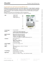
7. Take out the two antenna
cable connectors and
remove the locks and
protective sleeves. Then
connect them to the 4G/LTE
module.
8. Install the antenna cable connectors through the appropriate opening at the back of the chassis.
When leading the cable connector through the opening, check the socket alignment and only push
horizontally. DO NOT turn or twist the cable. Should any difficulties occur, make sure the surface is
clean. Finally, check the alignment again and carefully apply more force.
9. Use the lock to affix the
antenna from the outside.
10. Replace the case cover and fasten its screws.
11. Screw the antennas into
position as pictured. Make sure
they are aligned vertically to
achieve the best possible
signal reception.Make sure the
two antennas are aligned in
the correct direction.