- 11 -
3 HARDWARE INSTALLATION
Before removing or installing any of these devices including CPU, DIMMs, Add-On
Cards, Cables, please make sure to unplug the onboard power connector.
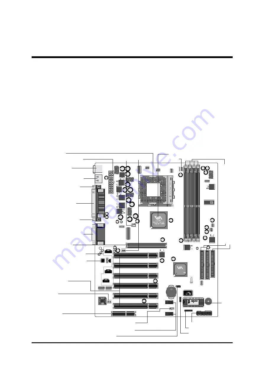
This section outlines how to install and configure your AK31 mainboard. Refer to the
following mainboard layout to help you identify various jumpers, connectors, slots, and
ports. Then follow these steps to guide you through a quick and correct installation of
your system.
3.1 Step-by-Step Installation
Accessories Of AK31
KEYBOARD & MOUSE
USB PORT
AGP 1
PCI 1
PCI 2
PCI 3
PCI 4
PCI 5
PCI 6
CNR1
COM1
COM2 PRINT
AUDIO
AJ1
J1
J1
KB1
USB1
JP6
V T8 2 33
0 02 1C G TA IW AN
1 3C ON 34 00
RST HLED
PLED
+ -
+ - + -
SPEAKER
GLED EPMI PWR ON
1 9 9 9
P C I / P N P K 7
2 0 2 0 6 2 2 6 9
JP8
JP9
JP7
CD_IN
AUX_IN
TAD I/O
1
1
1
1
1
1
JP4
IR
1
1
1
1
1
IDE2 IDE1 FDD
JP11
USB 5&6
USB 3&4
JP5
JP2
1
1
USB2
USB3
1
1
1
FAN2
FAN4
FAN3
FA
N1
DIM1
DIM2
DIM3
DIM4
UAM
34C-
ES
0032
94215
1
Panasonic
CR2032
3V
JAPAN1
ATX1
C
Pr
og
ra
m
m
ab
le
2M
b
Fl
as
h
EEP
RO
M
PS2 Keyboard/
PS/2 Mouse Connectors
USB1/USB2Connectors
Socket 462
Serial Port Connector
(COM1)
Serial Port Connector
(COM2)
Parallel Connector
VIA 8366 Chipset
On Board Audio CODEC
IR Header -
JP4
On Board Audio Header-
JP7, JP8, JP9
AGP 2x/4x Slot
Six PCI Slots
CNR Slot
ATX Power Connector
Line-In/Line-Out/Mic-In
Game/MIDI Connectors
Fl
op
py
C
onn
ec
to
r
Fo
ur
D
IMM sl
ot
s
Tw
o I
D
E C
onne
ct
or
s
FAN1
FAN4 FAN2
Front Ponel Header -
JP11
Clear CMOS -
JP2
BIOS Write Protection -
JP5
Wake On-Lan Connector -
JP6
Extended four USB Connector -
USB2/USB3
FAN3


