


Operation (Continued)
b. A flush must be provided for
fluids with a viscosity of greater
than 2000 SSU. The seal must be
cooled and lubricated by a fluid.
In the case of high viscosity fluids,
due to the precision clearances
between the gear teeth and the
body, highly viscous fluids will not
be able to adequately relieve the
air in the seal cavity on start-up.
The dry running of a mechanical
seal will cause rapid failure.
Pumping fluids with
viscosities greater than
2000 SSU requires flushing the seal chamber
during operation, otherwise seal damage
will occur.
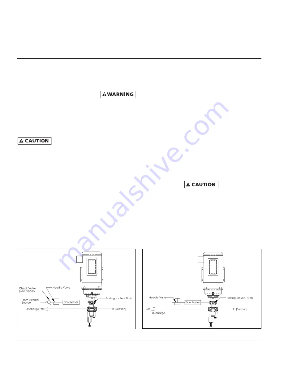
EXTERNAL FLUSH
An external flush system is typically
recommended for applications where
crystallization build-up on the seal is
possible. Some dilution of the working
material must be acceptable to use an
external flush system.
The external flush system (See Figure 5
for typical installation) is commonly
used with liquids where city water can
be used as the neutral flush fluid. City
water is taken from an external source
such as a tap, hose, or special plumbing
fixture and is regulated into the seal
cavity by means of a needle valve and
flowmeter. Use of an anti-siphon check
valve is required.
It is essential that an
anti-siphon check
valve be installed between the pump and
the city water supply to prevent any back
flow from possibly contaminating the city
water supply. Failure to do so could result in
contamination of the water supply with con-
sequential damages. Manufacturer assumes
no responsibility for failure of user in not
providing safeguards to city water systems.
Step 1:
Locate appropriate city water
supply and install anti-siphon check
valve.
Step 2:
Use appropriate pipe nipple to
reduce piping to 1/8”.
Step 3:
Install appropriate needle valve
and flowmeter.
Step 4:
Connect piping to one of three
available seal flush ports on pump.
Step 5:
Adjust needle valve to achieve
desired flow to seal cavity (recommend-
ed 1 to 3 GPH).
INTERNAL FLUSH
Similar to above but internal supply
(See Figure 6 for typical installation).
Typically recommended for high viscosity
applications ensuring lubrication to the
mechanical seal.
In an internal flush system, the fluid is
taken from the discharge and regulated
from 1 to 3 GPH (Gallons Per Hour) to
the seal cavity by means of a flowmeter
and needle valve.
Step 1:
Select a T pipe coupling that is
consistent with discharge pipe size and
material. Couple to discharge piping.
Step 2:
From this coupling, attach a
needle valve with appropriate nipple
reducing to 1/8” pipe or tube. Install
appropriate flowmeter.
Step 3:
Connect 1/8” pipe or tube to
one of three available seal cavity
flush ports.
Step 4:
Adjust needle valve to desired
flow into seal cavity (recommended
1 to 3 GPH).
For alternate flush
systems for hazardous
fluid applications, hot liquid transfer, and
those not addressed in this booklet, consult
a qualified fluid handling specialist for
assistance in specifying and installing flush
systems according to local, state and federal
environmental laws.
SHURflo Commercial-Duty Filter and Rendering Oil
Rotary Close-Coupled External Gear Pumps
8
Models NG7V, NG11V, NG7V-PH and NG11V-PH
SHURflo Operating Instructions, Performance,
Specifications and Parts Manual
Form L-4092 (3/10)
Figure 6 - Internal Flush
Figure 5 - External Flush


