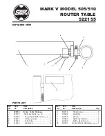
MARK V MODEL 505/510 ROUTER TABLE
522155
Page 8
ALIGNMENT
Your MARK V Model 505/510 Router Table
Attachment has been pre-aligned at our Day-
ton Factory, however, do to Environmental
changes, it may be necessary to make adjust-
ments as required.
If you find a step between the top surface of the
Saw Table and the Router Table, the Table
Tubes (3) of the Router Table must be adjusted
so that both table surfaces are even with each
other. To adjust the Router Table Tubes follow
these instructions.
1.
Place an accurate straightedge across the
top surfaces of both the Saw Table and
the Router Table. Make note as to where
the "gap" is.
2.
To adjust the Router Table parallel to the
Saw Table, loosen the Keps Nuts (6) that
hold the Table Tube (3) to the Router
Table. (See Figure 5)
6.
Tighten all the Jackscrews (4) of the Router
Table, in place.
7.
Slide the Connector Tubes into the Saw
Table Tubes. (See Figure 3)
8.
Tighten the Jackscrews (4) of the Saw
Table, to hold the Connector Tubes in
place.
9.
Attach a T-Joint, with Telescoping Leg, to
the Connector Tube extending from each
of the Router Table Tubes (3). Tighten the
T-Joint Set Screw with a 5/32” Allen
Wrench.
10.
Adjust each Telescoping Leg to support
the end of the Router Table. (See Figure 4)
Figure 2
Figure 3
11.
Locate the Router Table Plate Package
and follow the included instructions to
assemble and install the remaining parts
of the Router Table Plate. These instruc-
tions also give you the information
needed for mounting your Router and
aligning the Plate to the Table.
Figure 4
5.
Position both Connector Tubes evenly, so
that an equal amount is protruding from
both ends of the Router Table Tubes. (See
Figure 2)


