Shoprider XtraLite Jiffy UL7WR-10 Скачать руководство пользователя страница 11

8/18/2004 

11


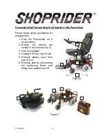
Drive/Freewheel Mechanism 

The drive/freewheel levers are found toward the front of the 
Powerchair, one on each side, located at the end of each motor.  
These levers will allow you to disengage the drive mechanism and 
push the Powerchair while in freewheel mode. 

 
Always leave the chair in drive mode.

  The freewheel option is 

there only to allow the chair to be pushed manually when the need 
arises (i.e., to store or push unit out of a tight space). 
 
The Powerchair will not function while the drive mechanism is 
disengaged.  In addition, the VSI-50 will flash a fault code and 
beep steadily if turned on.  Refer to Table 1 for more details. 


Figure 3 

Freewheel Lever 

Drive Powerchair 

Push Powerchair 

Содержание XtraLite Jiffy UL7WR-10

Страница 1: ...XtraLite Jiffy Portable Powerchair USER MANUAL Models UL7WR 10 UL7WR 12...

Страница 2: ...O KNOW YOUR JIFFY POWERCHAIR 9 THE JOYSTICK CONTROLLER VSI 9 DRIVE FREEWHEEL MECHANISM 11 USER TRANSFERRING 12 RECLINING SEAT 12 DISASSEMBLING TRANSPORTING YOUR JIFFY POWERCHAIR 13 DRIVING YOUR JIFFY...

Страница 3: ...tures support easy transportation of your Shoprider Powerchair for today s active lifestyle We know that it will provide many years of mobility for you This manual contains important information regar...

Страница 4: ...mounted directly on the transmitting unit Examples include citizens band CB radios walkie talkies security fire and police transceivers cellular telephones and other personal communication devices NOT...

Страница 5: ...ce the chance of unintended brake release or Powerchair movement which could result in serious injury 1 Do not operate hand held transceivers transmitter receivers such as citizens band CB radios or t...

Страница 6: ...immediately and could cause damage to the joystick controller 6 Do not drive over deep and soft terrain soft dirt loose gravel deep grass 7 Do not attempt to mount a curb height above 2 inches 8 Do n...

Страница 7: ...e the joystick 25 Always try to find a dropped curb or curb cutout whenever possible 26 Always keep your Powerchair properly maintained 27 Never try to use your Powerchair beyond it s limitations as d...

Страница 8: ...Access 2 VSI Joystick Controller 3 Charging Port 4 Reclining Pillow Top Leatherette Seat 5 Standard Foot Plate 6 Front Castor Assy 6 flat free tire 7 Frame Serial Number 13 alphanumeric characters 8...

Страница 9: ...5 Speed Decrease Button This button decreases the maximum speed 6 Speed Increase Button This Button Increases the maximum speed 7 Joystick This controls the speed and direction of the Powerchair Push...

Страница 10: ...ler bleeps Release the joystick there will be a long bleep The Powerchair controller is now locked To unlock the Powerchair controller Use the on off button to switch the controller on The maximum spe...

Страница 11: ...hile in freewheel mode Always leave the chair in drive mode The freewheel option is there only to allow the chair to be pushed manually when the need arises i e to store or push unit out of a tight sp...

Страница 12: ...ransfer Pull armrest up then push armrest forward and down for side transfer Reclining Seat The Jiffy Powerchair comes with a reclining seat The reclining seat lever is located on the left side below...

Страница 13: ...sembly 1 Park the Powerchair on a level surface 2 Ensure the wheels are locked in drive mode Fig 3 3 Fold up footplate 4 Unplug VSI from rear of unit 5 Remove battery pack from rear of unit 6 Remove s...

Страница 14: ...rough wet or slippery surface loose gravel tree roots wet grass polished floor etc 2 Always approach an incline head on not at an angle 3 Always travel at a speed that you are comfortable with and tha...

Страница 15: ...rchair are designed to be maintenance free and are sealed Therefore lubrication is not required for these components However the driving axles should always have a very light coat of multi purpose gre...

Страница 16: ...rom once a week to every other day the recharge point would be at 50 of discharge Refer to Figure 8 For extended battery life it is highly recommended that these guidelines be followed Keeping the bat...

Страница 17: ...essary for the battery pack to be attached to the Powerchair to charge The battery charger s light indicator is as follows Red Charging Green Charging complete Depending on the amount of battery disch...

Страница 18: ...your provider immediately Table 1 BATTERY GAUGE POSSIBLE VSI 50 FAULT 10 Bars flash Battery voltage is too high check the battery connections 9 Bars flash Solenoid brake fault 8 Bars flash Possible c...

Страница 19: ...based on user weight of 200 lbs 90 kgs 8 14 Range2 9 miles Turning Radius 29 inches As a part of our ongoing product improvement initiative Shoprider reserves the right to change specifications and de...

Страница 20: ...uthorized provider Maintenance records below should be kept at all times The manufacturer distributor vendor will be indemnified from any product liability claim if the above maintenance service requi...

Страница 21: ...__ Serial ____________________________________ Dealer Unit Was Purchased From ____________________________________ M D Y M D Y M D Y M D Y M D Y M D Y M D Y M D Y M D Y M D Y M D Y M D Y M D Y M D Y M...

Страница 22: ...Warranty is only valid when genuine Shoprider parts are used All modifications on the Powerchair unless approved and authorized by Shoprider will automatically invalidate the warranties Standard warr...

Отзывы: