background image

Air Conditioner Service Manmual

Length (m)

5

Gas additional charge(g/m)

40

Length (m)

15

Max Distance

Height (m)

5

Connection

Pipe

Gas Pipe (mm)

Φ

15.88(5/8'')

Outer Diameter

Liquid Pipe (mm)

Φ

9.52(3/8'')

Sound Pressure Level dB (A) (H/M/L)

60

Refrigerant Charge (kg)

1380

Net Weight /Gross Weight (kg)

50.2/54.3

Dimension of Package  (L/W/H)( mm)

1037x705x433

Dimension (W/H/D)  ( mm)

902x650x307

Sound Power Level dB (A) (H/M/L)

Defrosting Method

Auto defrost

Permissible Excessive Operating Pressure for
theSuction Side(MPa)

0.8

Permissible Excessive Operating Pressure for
theDischarge Side(MPa)

30

Moisture Protection

IP24

Isolation

I

Climate Type

T1

Output of Fan Motor (W)

95

Fan Diameter (mm)

φ

470×173

Fan Type

Axial fan

Air Flow Volume of Outdoor Unit(m3/h)

3350

Fan Motor Capacitor (

μ

F)

4

Fan Motor RLA(A)

0.92

Working Temp Range (ºC)

18-43

Fan Motor Speed (rpm)

850

Coil length (l) X height (H)Xcoil width (L)

901*609*19.05

Rows-Fin Gap(mm)

1-1.5

Pipe Diameter (mm)

Φ

9.52

Condenser

Hydrophilic aluminum fin-copper tube

60

Starting Method

Capacitor

Throttling Method

Capillary

Overload Protector

IOL

Compressor Type

Rotary

Compressor Model

ASH264SV-C8LU

Compressor Manufacturer/trademark

HIGHLY

Product Code

/

Outdoorunit

Model of Outdoor Unit

S

RH-I24

4

BE

Compressor Power Input(W)

2215

Compressor RLA(A)

10.3

L.R.A. (A)

13

Содержание SSH-I074BE

Страница 1: ...WALL MOUNTED SPLIT TYPE AIR CONDITIONERS Models SSH I074BE SSH I094BE SSH I124BE SSH I184BE SSH I244BE SSH L094DC SSH L124DC SERVICE MANUAL No TE121023 ...

Страница 2: ... information nor can it assume any liability in connection with its use The information specifications and parameter are subject to change due to technical modification or improvement without any prior notice The accurate specifications are presented on the nameplate label How to order spare parts To have your order filled promptly and correctly please furnish the following information 1 Model No ...

Страница 3: ...RH I124BE 18K Outdoor Unit 24K Outdoor Unit Remarks Fixed type 220 240V 50Hz I SSH I184BE O SRH I184BE I SSH I244BE O SRH I244BE I SSH L094DC W O SRH L094DC W DC inverter 220 240V 50Hz Models For DC inverter I SSH L124DC W O SRH L124DC W I SSH L094DC S O SRH L094DC S I SSH L124DC S O SRH L124DC S I SSH I074BE O SRH I074BE I SSH I094BE O SRH I094BE 3 ...

Страница 4: ... height H Xcoil width L 544 231 12 7 Ф7 Evaporator Hydrophilic aluminum fin copper tube Diameter Length mm φ88 8 545 Indoorunit Model of Indoor Unit SSH I074BE Fan Type Cross flow fan Fan Motor RLA A 0 16 Fan Motor Capacitor μF 1 5 Pipe Diameter mm Input of Heater W Fan Motor Speed r min SH H M L Output of Fan Motor W 12 Air Flow Volume m3 h Rated Frequency Energy Class A A EER C O P W W Dehumidif...

Страница 5: ...rge Side MPa 2 8 Air Flow Volume of Outdoor Unit m3 h 1415 Isolation I Climate Type T1 Defrosting Method Auto defrost Fan Diameter mm φ324 119 Fan Type Axial fan Rows Fin Gap mm 1 1 8 Fan Motor Capacitor μF 2 Fan Motor RLA A 0 37 Output of Fan Motor W 25 Fan Motor Speed rpm 895 Coil length l X height H Xcoil width L 621 462 12 7 Overload Protector B145 140 141E Pipe Diameter mm Φ7 Condenser Hydrop...

Страница 6: ...g Motor Model GBJDJ 01 0 16 Row Fin Gap mm 1 1 5 Pipe Diameter mm Ф7 Evaporator Hydrophilic aluminum fin copper tube EER C O P W W Fan Motor Capacitor μF 1 5 Input of Heater W Fan Motor Speed r min SH H M L Output of Fan Motor W 12 Indoorunit Model of Indoor Unit SSH I094BE Energy Class A A Diameter Length mm φ88 8 545 Fan Type Cross flow fan Fan Motor RLA A Product Code 1 0 Total Capacity W Power...

Страница 7: ...Axial fan Moisture Protection IP24 Isolation I Climate Type T1 Defrosting Method Auto defrost Fan Diameter mm φ324 119 Coil length l X height H Xcoil width L 621 462 12 7 Air Flow Volume of Outdoor Unit m3 h 1415 Fan Motor Capacitor μF 2 Fan Motor RLA A 0 37 Output of Fan Motor W 25 Fan Motor Speed rpm 895 Throttling Method Capillary Rows Fin Gap mm 1 1 8 Pipe Diameter mm Φ7 Condenser Hydrophilic ...

Страница 8: ...in copper tube Diameter Length mm φ90 8 602 SSH I124BE Fan Type Cross flow fan Fan Motor RLA A 0 16 Fan Motor Capacitor μF 1 5 Fan Motor Speed r min SH H M L Output of Fan Motor W 12 Rated Input W Rated Current A Air Flow Volume m3 h Input of Heater W Indoorunit Model of Indoor Unit Pipe Diameter mm Swing Motor Model Sound Pressure Level dB A H M L Dimension of Package L W H mm Energy Class A A EE...

Страница 9: ...ischarge Side MPa 2 9 Moisture Protection IP24 Isolation I Climate Type T1 Output of Fan Motor W 31 Fan Diameter mm φ401 119 Fan Type Axial fan Air Flow Volume of Outdoor Unit m3 h 2040 Fan Motor Capacitor μF 2 5 Fan Motor RLA A 0 45 Working Temp Range ºC 18 43 Fan Motor Speed rpm 860 Coil length l X height H Xcoil width L 711 504 12 7 Rows Fin Gap mm 1 1 5 Pipe Diameter mm Φ7 Condenser Hydrophili...

Страница 10: ...ng Motor Model GBJDJ 01 L 0 30 Row Fin Gap mm 2 1 6 Pipe Diameter mm Ф7 Evaporator Hydrophilic aluminum fin copper tube EER C O P W W Fan Motor Capacitor μF 1 5 Input of Heater W Fan Motor Speed r min SH H M L Output of Fan Motor W 23 Indoorunit Model of Indoor Unit SSH I184BE Energy Class A A Diameter Length mm φ94 709 Fan Type Cross flow fan Fan Motor RLA A 1 15 Total Capacity W Power Input W Ra...

Страница 11: ...Type Axial fan Moisture Protection IP24 Isolation I Climate Type T1 Defrosting Method Auto defrost Fan Diameter mm φ409 132 Coil length l X height H Xcoil width L 768 510 19 05 Air Flow Volume of Outdoor Unit m3 h 2340 Fan Motor Capacitor μF 3 Fan Motor RLA A 0 47 Output of Fan Motor W 45 Fan Motor Speed rpm 850 Throttling Method Capillary Rows Fin Gap mm 1 1 5 Pipe Diameter mm Φ9 52 Condenser Hyd...

Страница 12: ...fin copper tube Diameter Length mm φ94 709 SSH I244BE Fan Type Cross flow fan Fan Motor RLA A 0 30 Fan Motor Capacitor μF 1 5 Fan Motor Speed r min SH H M L Output of Fan Motor W 23 Rated Input W Rated Current A Air Flow Volume m3 h Input of Heater W Indoorunit Model of Indoor Unit Pipe Diameter mm Swing Motor Model Sound Pressure Level dB A H M L Dimension of Package L W H mm Energy Class A A EER...

Страница 13: ...for theDischarge Side MPa 30 Moisture Protection IP24 Isolation I Climate Type T1 Output of Fan Motor W 95 Fan Diameter mm φ470 173 Fan Type Axial fan Air Flow Volume of Outdoor Unit m3 h 3350 Fan Motor Capacitor μF 4 Fan Motor RLA A 0 92 Working Temp Range ºC 18 43 Fan Motor Speed rpm 850 Coil length l X height H Xcoil width L 901 609 19 05 Rows Fin Gap mm 1 1 5 Pipe Diameter mm Φ9 52 Condenser H...

Страница 14: ... length l X height H Xcoil width L 657x315x25 4 Row Fin Gap mm 2 1 5 Pipe Diameter mm Ф7 EER C O P W W Fan Motor Capacitor μF 1 5 Input of Heater W Fan Motor Speed r min SH H M L Output of Fan Motor W 18 Indoorunit Model of Indoor Unit Energy Class A A Diameter Length mm φ98 622 Fan Type Cross flow fan Fan Motor RLA A 0 23 0 9 Total Capacity W Power Input W Rated Input W Rated Current A Air Flow V...

Страница 15: ...a 1 9 Fan Type Axial fan Moisture Protection IP25 Isolation I Climate Type T1 Defrosting Method Auto defrost Fan Diameter mm φ408 132 Coil length l X height H Xcoil width L 756x510x25 4 Air Flow Volume of Outdoor Unit m3 h 2340 Fan Motor Capacitor μF 2 5 Fan Motor RLA A 0 45 Output of Fan Motor W 31 Fan Motor Speed rpm 860 Throttling Method Capillary Rows Fin Gap mm 2 1 5 Pipe Diameter mm Φ7 Conde...

Страница 16: ...x25 4 Row Fin Gap mm 2 1 5 Ф7 Evaporator Hydrophilic aluminum fin copper tube Diameter Length mm φ98 622 Cross flow fan Fan Motor RLA A 0 23 Fan Motor Capacitor μF 1 5 Fan Motor Speed r min SH H M L Output of Fan Motor W 18 Rated Input W Rated Current A Air Flow Volume m3 h Input of Heater W Indoorunit Model of Indoor Unit Fan Type Pipe Diameter mm Swing Motor Model Sound Pressure Level dB A H M L...

Страница 17: ...4 5 Moisture Protection IP26 Isolation I Climate Type T3 Output of Fan Motor W 30 Fan Diameter mm φ408 132 Fan Type Axial fan Air Flow Volume of Outdoor Unit m3 h 2340 Fan Motor Capacitor μF 2 5 Fan Motor RLA A 0 45 Working Temp Range ºC 18 45 Fan Motor Speed rpm 900 770 670 Coil length l X height H Xcoil width L 756x510x25 4 Rows Fin Gap mm 2 1 5 Pipe Diameter mm Φ7 Condenser Hydrophilic aluminum...

Страница 18: ...Louver Pipes and Power Air Conditioner Service Manual 18 ...

Страница 19: ...Air Conditioner Service Manmual 19 ...

Страница 20: ... I K J D E Unit mm Capacity A B C D E F G H I J K 7K 9K 718 240 180 600 500 230 271 296 52 376 55 12K 770 240 180 700 552 256 290 328 48 439 2 55 18K 898 280 202 760 552 256 290 328 48 507 8 63 24K 898 280 202 902 650 307 349 399 65 753 5 63 Air Conditioner Service Manual 20 ...

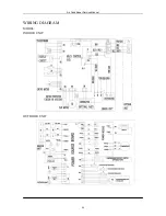
Страница 21: ...Air Conditioner Service Manual WIRING DIAGRAM MODEL SSH I074BE SSH I094BE SSH I124BE INDOOR UNIT OUTDOOR UNIT 21 ...

Страница 22: ...Air Conditioner Service Manual WIRING DIAGRAM MODEL SSH I184BE INDOOR UNIT OUTDOOR UNIT 22 ...

Страница 23: ...Air Conditioner Service Manual WIRING DIAGRAM MODEL SSH I244BE INDOOR UNIT OUTDOOR UNIT 23 ...

Страница 24: ...duct Dimensions Outdoor Unit Indoor Unit A B 20 mm 400 mm 57 mm C H G F I K J D E Unit mm Capacity A B C D E F G H I J K 9K 12K 800 280 185 760 552 256 290 328 48 507 8 63 Air Conditioner Service Manual 24 ...

Страница 25: ...Air Conditioner Service Manual WIRING DIAGRAM MODEL SSH L094DC W SSH L094DC S INDOOR UNIT OUTDOOR UNIT 25 ...

Страница 26: ...Air Conditioner Service Manual WIRING DIAGRAM MODEL INDOOR UNIT OUTDOOR UNIT 26 ...

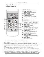
Страница 27: ...ss any button when the arrowhead flashes on the front of Cool Cooling Only is set Press any button when the arrowhead flashes on the front of Heat Heat Pump is set If you don t press any button within 10 seconds the remote controller is preset as Heat Pump automatically Note If the air conditioner you purchased is a Cooling Only one but you preset the remote controller as Heat Pump it doesn t brin...

Страница 28: ... Initial RT Initial ST Cooling RT 26 23 Dehumifying 26 RT 20 18 Heating RT 20 23 Cooling only Mode Initial RT Initial ST Cooling RT 26 23 Dehumifying 26 RT 20 18 Ventilating RT 20 Under automatic mode including from automatic converted into dehumidifying Dry mode when the temperature up and down signals from the remote controller is received the setting temperature ST adjusts correspondingly to th...

Страница 29: ...ure changes lead to changes in airflow speed the switch can only be made orderly and every grade of air flow speed runs 1 minute at least 4 Vane motor control run as set state 5 4 way valve control a Under heating mode the four way valve maintains well connected status including the compressor stops on set condition but except for the defrosting process b When the mode switches into the heating mo...

Страница 30: ... temperature droping when compressor operating not including the compressor s starting course and the machine runs into defrosting according to any one condiciton as below Running into defrosting under condition 3 defrosting time set is 10 min a Running into the first defrosting in 20 min after start up b The interval from last defrosting equivalent to or more than 50 min stopping the compressor o...

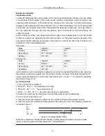
Страница 31: ...quitting conditions for option 3 When OPT 20 C or defrosting for more than 10 min then quit from defrosting 3 Defrosting process shown in Figure 4 Figure 4 Defrosting process 7 Auxiliary Electric heating function 1 The default condition is automatic on off the electric heating function 2 The conditions of auxiliary electric heating all the following conditions must be met a the compressor runs for...

Страница 32: ...ding on the buzzer rings twince then the machine runs into heating mode while when the machine is on to press the emergency Switch the buzzer rings once and then the machine shut down 2 The machine is running mandatorily as the selected mode within 30min after emergency operation indoor fan motor is running in high speed and vane board is swinging The machine runs into automatic mode 30min later t...

Страница 33: ... and the compressor open indoor fan motor restores the original state 4 Anti cold wind control in heating a When runing into the heating mode once the compressor fails to comply with the start up conditions the wind speed is regulated according to the coil temperature in 2 min including stopping the indoor fan motor 2 min later the indoor fan motor stops If the compressor starts up within 2 min th...

Страница 34: ...r failures appear the compressor stops and indoor and outdoor fan motors shut off Remote controller deesn t response to any signal except for shutdown During failure the machine can run in fan mode After the failure is settled the PCB restores to standby status b Failure protection of Indoor PG fan motor If there is no feedback signal of rotate speed within 5 the indoor fan motor stops at the same...

Страница 35: ...Air Conditioner Service Manual EXPLOSION VIEW MODEL SSH I074BE SSH I094BE SSH I124BE SSH I184BE INDOOR UNIT 15 6 14 11 13 12 8 10 9 7 1 5 4 3 2 19 18 17 16 23 24 21 20 22 26 25 27 35 ...

Страница 36: ...Air Conditioner Service Manual EXPLOSION VIEW Model SRH I244BE INDOOR UNIT 15 6 14 11 13 12 8 10 9 7 1 5 4 3 2 19 18 17 16 23 24 21 20 22 26 25 36 ...

Страница 37: ...Air Conditioner Service Manual EXPLOSION VIEW Mode SSH I074BE OUTDOOR UNIT 27 8 1 28 2 3 4 26 24 25 23 22 20 21 17 18 16 15 19 5 6 7 9 11 10 14 13 12 37 ...

Страница 38: ...Air Conditioner Service Manual EXPLOSION VIEW MODEL SSH I0934E SSH I184BE OUTDOOR UNIT 10 11 12 8 9 7 6 5 17 13 14 16 15 19 18 20 21 23 22 24 4 3 2 25 26 27 1 38 ...

Страница 39: ...Air Conditioner Service Manual EXPLOSION VIEW Model SRH I124BE OUTDOOR UNIT 11 12 13 9 10 8 7 6 5 18 14 15 17 16 20 19 21 22 24 23 25 4 3 2 26 1 39 ...

Страница 40: ...Air Conditioner Service Manual EXPLOSION VIEW MODEL SSH I244BE OUTDOOR UNIT 27 1 26 25 23 24 22 21 2 3 19 18 17 16 15 13 12 14 20 4 5 7 6 9 8 11 10 40 ...

Страница 41: ... 1170120044 Power Supply Cord 1 16 1070250416 Vane 1 17 1070110011 Drainage Hose 1 18 1070040004 Cable Clamp 1 19 1090200112 Main PCB 1 20 1070320113 Electrical Box 1 21 1170020011 Vane Motor 1 22 1073030201 Sensor Holder 1 23 1170030047 Indoor Motor 1 24 1070320111 Indoor Motor Cover 1 25 1170240001 Transformer 1 26 1170230001 Indoor Sensor Assembly 1 27 1070320101 In And Out Pipe Fixer 1 28 1090...

Страница 42: ... 1170120044 Power Supply Cord 1 16 1070250416 Vane 1 17 1070110011 Drainage Hose 1 18 1070040004 Cable Clamp 1 19 1080250433 Main PCB 1 20 1070320113 Electrical Box 1 21 1170020011 Vane Motor 1 22 1073030201 Sensor Holder 1 23 1170030047 Indoor Motor 1 24 1070320111 Indoor Motor Cover 1 25 1170240001 Transformer 1 26 1170230001 Indoor Sensor Assembly 1 27 1070320101 In And Out Pipe Fixer 1 28 1090...

Страница 43: ...5 1170120045 Power Supply Cord 1 16 1070320439 Vane 1 17 1070110011 Drainage Hose 1 18 1070320114 Cable Clamp 1 19 1090320619 Main PCB 1 20 1070320113 Electrical Box 1 21 1170020011 Vane Motor 1 22 1073030201 Sensor Holder 1 23 1170030047 Indoor Motor 1 24 1070320111 Indoor Motor Cover 1 25 1170240001 Transformer 1 26 1170230001 Indoor Sensor Assembly 1 27 1070320101 In And Out Pipe Fixer 1 28 109...

Страница 44: ...ord 1 16 1070350140 Vane 1 17 1070110011 Drainage Hose 1 18 1070040004 Cable Clamp 1 19 1090500220 Main PCB 1 20 1070451080 Electrical Box 1 21 1170020041 Vane Motor 2 22 1073030201 Sensor Holder 1 23 1170030065 Indoor Motor 1 24 1070350152 Indoor Motor Cover 1 25 1170240001 Transformer 1 26 1170230001 Indoor Sensor Assembly 1 27 1070350245 In And Out Pipe Fixer 1 28 1090050298AN Remote Controller...

Страница 45: ...40 Vane 1 16 1070110011 Drainage Hose 1 17 1070040004 Cable Clamp 1 18 1090640002 Main PCB 1 19 1070451080 Electrical Box 1 20 1170020041 Vane Motor 2 21 1073030201 Sensor Holder 1 22 1170030065 Indoor Motor 1 23 1070350152 Indoor Motor Cover 1 24 1170240001 Transformer 1 25 1170230001 Indoor Sensor Assembly 1 26 1070350245 In And Out Pipe Fixer 1 27 1090050298AN Remote Controller 1 28 1070060003 ...

Страница 46: ...2 Right Plate 1 16 1120120025 Two way Valve 1 17 1081990013 Valve Supporter 1 18 1120130039 Three way Valve 1 19 1073521301 Electrical Box Cover 1 20 1070040001 Cable Clamp φ6 1 21 1070040002 Cable Clamp φ7 1 22 1170500131 Terminal 1 23 1170100031 Fan Motor Capacitor 1 24 1170100014 Compressor Capacitor 1 25 1080010002 Capacitor Strip 1 26 1081990010 Electrical Parts Box 1 27 1120200361 Capillary ...

Страница 47: ... 1120120025 Two way Valve 1 16 1081990013 Valve Supporter 1 17 1120130039 Three way Valve 1 18 1070350971 Electrical Box Cover 1 19 1070040001 Cable Clamp φ6 1 20 1070040002 Cable Clamp φ7 1 21 1170500131 Terminal 1 22 1170100031 Fan Motor Capacitor 1 23 1170100026 Compressor Capacitor 1 24 1080010006 Capacitor Strip 1 25 1081990010 Electrical Parts Box 1 26 1120251548 Capillary Assembly 1 27 1081...

Страница 48: ... Right Plate 1 15 1120120021 Two way Valve 1 16 1080050003 Valve Supporter 1 17 1121990040 Three way Valve 1 18 1070350971 Electrical Box Cover 1 19 1070040001 Cable Clamp φ6 1 20 1070040003 Cable Clamp φ8 1 21 1170500131 Terminal 1 22 1170100010 Fan Motor Capacitor 1 23 1170100003 Compressor Capacitor 1 24 1080010006 Capacitor Strip 1 25 1080020001 Electrical Parts Box 1 26 1120351011 Capillary A...

Страница 49: ...5 1120120021 Two way Valve 1 16 1080050003 Valve Supporter 1 17 1120130032 Three way Valve 1 18 1070350971 Electrical Box Cover 1 19 1070040001 Cable Clamp φ6 1 20 1070040003 Cable Clamp φ8 1 21 1170500131 Terminal 1 22 1170100027 Fan Motor Capacitor 1 23 1170100025 Compressor Capacitor 1 24 1080010006 Capacitor Strip 1 25 1081990010 Electrical Parts Box 1 26 1120501358 Capillary Assembly 1 27 108...

Страница 50: ...e 1 15 1120120024 Two way Valve 1 16 1081990041 Valve Supporter 1 17 1120130037 Three way Valve 1 18 1070350971 Electrical Box Cover 1 19 1074060118 Cable Clamp 1 20 1170200054 Terminal 1 21 1170100030 Fan Motor Capacitor 1 22 1170100007 Compressor Capacitor 1 23 1080010004 Capacitor Strip 1 24 1081990049 Electrical Parts Box 1 25 1174561801 AC Contactor 1 26 1120701000 Capillary Assembly 1 27 108...

Страница 51: ...lows Press any button when the arrowhead flashes on the front of Cool Cooling Only is set Press any button when the arrowhead flashes on the front of Heat Heat Pump is set If you don t press any button within 10 seconds the remote controller is preset as Heat Pump automatically Note If the air conditioner you purchased is a Cooling Only one but you preset the remote controller as Heat Pump it does...

Страница 52: ...s overload controller shut down the unit immediately and show error code 6 Compressor abnormity protection When compressor start on or in the process of running if there is no feedback to controller or load of compressor is abnormity the air conditioner will shut down and show error code 7 IPM module protection IPM module has high temperature over current protection itself if there is signal feedb...

Страница 53: ...will run automatically 3 Auto fan control in cooling mode In cooling mode include cooling in I feel mode fan speed is determined by δt as the following diagram 1 5 1 0 3 0 3 5 δt come down high fan δt come up midium fan low fan RT ST 4 DRY Mode Operation 1 The system for DRY operation used the same refrigerant circle as the cooling one 2 When the system operates in DRY mode at first it operates in...

Страница 54: ...rocess of defrosting 4 Defrosting Defrosting is controlled by the microprocessor When one of the following conditions is satisfied unit will come into defrosting a Outdoor heat exchanger Temperature OPT is continuously less than 3 while the unit runs for more than 40 minutes and OPT is keeping under 6 for more than 3 minutes b Outdoor heat exchanger Temperature OPT is continuously less than 3 mean...

Страница 55: ...ater z When selecting HEATING operation with SLEEP mode the set temperature will be dropped by 1 1 hour later and 2 2hour later z After the System operates in SLEEP mode for 8 hours it will stop automatically 7 EMERGENCY Operation When the EMERGENCY Operation switch is pressed once COOLING mode is selected and if in 3 seconds the EMERGENCY Operation switch is pressed again mode is selected Then pr...

Страница 56: ...of the error list z Protection display function can be selected in hardware and the default don t display z To insure of in and out communist is credibility the failures relate to outdoor unit will remain failure state for 2 minutes max after recovered z In all failures only sensor failures don t have to repower to cancel z Error list Failure type LED CODE DIGITAL LED CODE In and out communication...

Страница 57: ...door power board when compressor is running it is normally light when no feedback of signal to power board from compressor it will wink by lighting 1s and going out 1s If failures happened it will light 0 5s go out 0 5s winking several times and go out 3s for a cycle to indicate failures The failure list is the follow Wink time Failure 1 IPM protection 2 higher or lower voltage 3 Over current 4 Di...

Страница 58: ...Air Conditioner Service Manual EXPLOSION VIEW Mode SSH L094DC W SSH L124DC S INDOOR UNIT 15 6 14 11 13 12 8 10 9 7 1 5 4 3 2 19 18 17 16 23 24 21 20 22 26 25 27 58 ...

Страница 59: ...1 16 Drainage Hose 1 17 Cable Clamp 1 18 Terminal 1 19 Terminal fixing board 1 20 Main PCB digital 1 21 Electrical Box 1 22 Vane Motor 2 23 Sensor Holder 1 24 Indoor Motor 1 25 Indoor Motor Cover 1 26 Transformer 1 27 Indoor Sensor Assembly 1 28 In and out fixer 1 29 Remote Controller 1 30 Remote Controller Supporter 1 31 Indoor Carton 1 32 Left Foaming 1 33 Right Foaming 1 34 Middle Pasteboard Su...

Страница 60: ...Air Conditioner Service Manual EXPLOSION VIEW MODEL SSH L094DC W SSH L094DC S OUTDOOR UNIT 10 11 12 8 9 7 6 5 17 13 14 16 15 19 18 20 21 23 22 24 4 3 2 25 26 1 27 60 ...

Страница 61: ...ssembly 1 13 Base 1 14 Right plate 1 15 Two way valve 1 16 Valve supporter 1 17 Three way valve 1 18 Electrical Box Cover 1 19 Cable clamp 1 20 Terminal 1 21 Electrical box 1 22 Inverter module 1 23 Power source board 1 24 Radiator 1 25 Inductor 1 26 Capillary assembly 1 27 Partition plate 1 28 Pipe Temp sensor and outdoor Temp sensor 1 29 Discharge Temp sensor 1 30 Base carton 1 31 Cabinet carton...

Страница 62: ...ANNEX 1 TROUBLE SHOOTING INDEX 1 Electric parts 2 Refrigerant system 3 Troubleshooting 4 Installation Fundamentals Air Conditioner Service Manual 62 ...

Страница 63: ...n Usable voltage Product rating 10 2 Electric wire capacity The electric wire for airconditioner should have an allowable current more than the load current of the circuit and be able to control the voltage drop by the load current within 2 And it should be a thickness capable of keeping the voltage drop by a starting current within 10 and espe cially for an airconditioner of single phase the volt...

Страница 64: ... 2 Insulation resistance measurement of compressor Measure the insulation resistance of compressor between compressor terminal and dead metal part by insu lation resistor and the insulation resistance should be above 10MΩ Compressor may change the insulation resistance while running Accordingly measure the insulation resistance just after running as needed Note For R 22 used in airconditioner the ...

Страница 65: ...hree kinds of dial vibrating direction in tester and each vibrating direction and symptom is as follows A Normal Dial shakes instantaneously and returns to the original state immediately B Short Dial remains moved C Capacity consumed up Dial does not move at all 1 2 4 Motor fan 1 Power off remove motor fan and test independently 2 Measure the resistance of main coil sub coil and control coil in mo...

Страница 66: ... If knob is turned but click does not sound remove the thermostat cover and examine the contact point The fused contact point should be replaced with a new thermostat If contact point is not closed despite of the sensor temperature being sufficiently high the gas at the sensor part may be leaked In this case replace the thermostat When replacing thermostat be sure to conduct after performing caref...

Страница 67: ... motor inside and for a single phase compressor with O L P built in it identifies the O L P operating condition and wire disconnection 1 Shut off the power supply to product 2 Remove the wires connected to the compres sor terminal 3 After checking the ground state cool the compressor sufficiently at room temperature For single phase compressor 4 Measure the resistance of each terminal by Ohm meter...

Страница 68: ...mperature of discharge pipe in compressor and if it is abnormally low temperature 50 C or less the compressor is bad c Conduct the pump down test of system to check the compression capacity Power off the product Close the service valve of liquid line Rotate the valve rod clockwise to close the valve rod Start product and observe the suction pressure If compressor is normal by pumping down the syst...

Страница 69: ...r in indoor unit Adjust the wind direction so that wind is discharged to the front direction in the installed condition b Measure the voltage and current in running condition c Measure the pressure of low pressure side in cooling condition If the temperature is low convert into the test switch 2 1 1 Temperature difference and current of suction discharge air in evaporator Temperature difference of...

Страница 70: ...figure converted into pressure The low pressure is normally 4 5 6 0kg cm2G Temperature is normally 3 C 10 C Indoor Side Outdoor Side Evaporator Compressor Capillary Tube High pressure Liquid side tube Low pressure Gas side tube Accumulator Compressor P1 P2 Measuring place Pressure kg cm2 G P1 About19 5 P2 About 5 0 Pressure Temperature Cause Explanation than normal than normal Higher Higher Bad co...

Страница 71: ...oil comes out from the evaporator condenser connections and each welded portion Finding the gas leak place 3 Actions Find the gas leak area Check at balance pressure of 5kg cm2 G or over Charge refrigerant to the specified level Check for gas leak 2 Closing of refrigerant system 1 Symptoms If the refrigerant system of strainer or capillary tube is closed pressure drops at the outlet of closed area...

Страница 72: ... Check for gas leak 4 Bad compression 1 Symptoms The temperature difference of suction discharge air is little the running current is less than the specified current the pressure of high pressure side is low and the pressure of low pressure is high 2 Judgement method Close service valve of high pressure side in condenser front seat and connect the manifold gauge to the service valve of low pressur...

Страница 73: ...ould direct the direction where nobody exists 2 Do not work near fire or flame 3 Work in a large space if possible and arrange the scaffold 4 Especially for working on rooftop prepare a place to keep tools and take care to prevent from falling 5 While running pump down work test run do not insert hands into fan 6 Clean the Indoor outdoor connecting pipes and the manifold gauge edges to be free fro...

Страница 74: ...voltage Driving load terminal Display PCB connector Power receptable voltage Product input voltage Evaportor condenser connecting pipe PCB assy fuse varistor pattern AC about 14 3V General model Connector contact check Power trans output voltage PCB assy check Air Conditioner Service Manual 74 ...

Страница 75: ...or capacitor Communication effor Blower lock sensing In dehumidifying heating or artificial intelligence operation room fan may be off Coil resistance TP Motor capacitor Motor insulation resistance Motor related parts check Motor detail check Error code check PCB ass y check Operation mode check Motor driving circuit Relay output Air Conditioner Service Manual 75 ...

Страница 76: ...sensor open close check Connector check Contact power Disconnection short circuit check of connecting wire Electric wire connection check for outdoor side Compressor motor detail check Repeat running stopping at a short time period Thermistor and evaporator surface contact check Clearance is needed 5mm Connector check Contact power OLP High pressure switch Low pressure switch check Operation mode ...

Страница 77: ...al At the moment the blower is stopped up down vane auto switch is stopped and if blower is started auto switch is re operated Especially it occurs while dehumidifying or heating Motor shaft assembly check Connector check Disconnection short circuit malconnection Blower operating condition check PCB ass y check Step motor driving circuit Air Conditioner Service Manual 77 ...

Страница 78: ...the room fan is stopped louver auto swing is stopped and if room fan is started auto swing is re operated Especially it occurs while dehumidifying or heating Motor shaft assembly check Connector check Disconnection short circuit malconnection Blower operating condition check PCB ass y check Step motor driving circuit Synchronous motor driving circuit Air Conditioner Service Manual 78 ...

Страница 79: ...if compressor is stopped blower is operated at low fan In dehumidifying mode to enhance the dehumidifying effect blower is operated at low fan In heating mode blower is stopped or operated at low fan according to the situations defrosting hot start compressor off In Sleep operation mode blower is operated without switched over low or middle fan In artificial intelligence mode room fan switching ov...

Страница 80: ...operation by remocon and after about 30 sec check the 4 way valve relay output 4 way valve OFF If 4 way valve is OFF the refrigerant flowing sounds pee due to cycle switchover occurs If the reversing valve 4 way valve is ON tick sounds Connector check PCB ass y check 4 way valve coil resistance check 4 way valve relay output ON Air Conditioner Service Manual 80 ...

Страница 81: ...lared copper pipes with non rectangular section Troubles Causes Defect Details Guidelines Pipe cutter Pipe cutter Make pipe straight before cutting and it makes a rectangular section Cu pipe Cu pipe Cutting curved pipe leads mal rectangular section And it makes gas leakage Air Conditioner Service Manual 81 ...

Страница 82: ...roubles Causes Defect Details Guidelines Reamer Burrs should be removed clearly with REAMER Only clean surfaces prevent gas leakages Burrs not removed properly after cutting Flaring the pipe with burrs not removed after cutting can make freon gas leakages Burrs won t make smooth contacting surfaces Air Conditioner Service Manual 82 ...

Страница 83: ...izes for several pipes which make proper connectings a Pipe dia b Hight c Flared dia Pipe worked with large sized b won t be assemsled into the nut Pipe worked with small sized b will make small contact with nut and gas leak against even a weak shock ø6 35 ø9 52 ø12 70 ø15 8 ø19 05 1 0 1 3 0 8 1 0 0 5 0 8 0 5 0 8 0 0 5 8 3 8 7 12 0 12 4 15 4 15 8 18 6 19 0 23 3 22 9 unit mm Air Conditioner Service...

Страница 84: ...ue wrench is required for proper fastenings Check gas leakages of 4 fastened points and welded points with soap bubbles ctc High pressure points amid compressor s running Low pressure points amid compressor s not running Tube Dia mm Torques Kg Cm 6 35 160 200 9 52 350 450 15 88 450 550 19 05 550 650 Damaged Flares by over fastening Incompletely fastened nuts Indoor Side Outdoor Side Air Conditione...

Страница 85: ...ed For a better drain the install plate may be tilted 2 3 to drain pan s drain side Install plate Weight Confirm the water draining is good or not by poring water into the drain pan Connecting parts of drain pan and hose should be well fixed with bond for waterproofing 2 Mal linked drain hose 1 Non leveled indoor Horizon Evaporator Drain pan Connect hoses with drain pan drainage leaks Slanted Air ...

Страница 86: ...s Causes Defect Details Guidelines Connect the extending hose outside and seal with bond and finish by taping Install the drain hose straightened and downward 2 Curved or upward drain hose 1 Improperly extended drain hose Extending hose Extending hose Downward Drain hose Water leaks through the inside connected drain hose Drain hose Air Conditioner Service Manual 86 ...

Страница 87: ... and ending Troubles Causes Defect Details Guidelines The wall through hole should be downward Don t make drain hose clogged with water 2 Clogged drain hose with water 1 Upwarded drain hose along the wall through hole Downward Arrange gap Drainage can t flow down across the wall Drainage can t flow down along the hose Air Conditioner Service Manual 87 ...

Страница 88: ...mpletely insulate weak points like pipe connection and hidden parts Ceiling Hidden parts like behind the ceiling is a weak point too 2 Un insulated hidden parts 1 Incomplete insulation works on tube connecting parts Use designated insulations on pipe connecting parts Drainage flows down from incompletely insulated parts Drainage flows down from the hidden parts Ceiling Air Conditioner Service Manu...

Страница 89: ...Defect Details Guidelines Make U trap against the waterdrop inflow tapings should be upward form downside Outdoor unit Indoor unit U trap 1 Pipe from upside lead waterdrops rain drainage etc into the room 2 Wrong taping direction lead waterdrops into the room too Taping direction Upward Downward Waterdrops outdoor unit Outdoor unit Air Conditioner Service Manual 89 ...

Страница 90: ...nding tubings For a simple check of proper freon quantity com pare the in and out air temperature after 15 m in from com pressor s running Air in Detect the gas leakages before insulation tubing confirm new welded points 1 Not adding freon for extended tubings 2 Gas leakage on welded points for extending tubings Temp diff Cooling 8deg Heating 14deg Air out Air Conditioner Service Manual 90 ...

Страница 91: ...ils Guidelines Ensure the distance needed for air flows Bad air flows lead cooling capacity s drop The product may not run normally as the accumulated heat make compressor stop by protecting device s work like PTC 1 The space for air intake is too narrow 2 The space for air discharge is too narrow 10cm 50cm Wall Wall Wall Wall Air Conditioner Service Manual 91 ...

Страница 92: ...ails Guidelines Ensure not to disturb the air intake flows Ensure not to disturb the air discharge flows The awning is recommended for a optimum cooling 1 The space for air intake is too narrow Closed air intake flow Closed air discharge flow 2 The space for air discharge is too narrow Air intake holes 30cm Wall Wall Wall Wall Air Conditioner Service Manual 92 ...

Страница 93: ...utdoor unit Troubles Causes Defect Details Guidelines Discharged air should be outward and not disturbed Establish a proper awning 1 The outdoor shut in a verandah does not work normally The air around the outdoor unit arise too high Living 2 Improper awning Living room 30cm Verandah Verandah Wall Air Conditioner Service Manual 93 ...

Страница 94: ...lines To get a good shaped tube after bending use specified spring or bending tools In changing air conditioning unit the tubes too should be changed with proper ones 1 Crushed tube by improper bending works 2 Changed tubing from specified tubes Not using proper tubes designed for each product Crushed area Spring for bending Bending tool Air Conditioner Service Manual 94 ...

Страница 95: ...nstalled too high beyond recommended height difference between indoor and outdoor unit Higher than recommended Nth 3rd 2rd 1st floor Recommending maximum distances between indoor and outdoor unit RAC Split vertical 5m horizontal 10m PAC 3 0 HP Ø Ø vertical 5m horizontal 10m PAC 3 5 Hp Ł Ł vertical 5m horizontal 20m Air Conditioner Service Manual 95 ...

Страница 96: ...ils Guidelines 1 Unstable installed outdoor unit 2 Released fittings and fasteners Slanted Parallel Duct Indoor unit Install the unit balanced stably using specified legs etc To prevent vibrations and noises fasten tightly all the connecting parts for electric heater steam line air duct line etc Air Conditioner Service Manual 96 ...

Страница 97: ...Defect Details Guidelines Unstable fixing of surplus tubings will make vibrations and noises during the compressor s running Fixing band Cut away the surplus tubings But if there are any surplus tubings left for some reasons be sure to fix them stably with fixing bands Air Conditioner Service Manual 97 ...

Страница 98: ...d screws of electric power lines It can be led to critical accidents 2 Wiring mistake of fan s electric power lines for outdoor Fan rotates reversely and the unit will be shutdown with overload Air discharge Reversed flow Circu it breaker Exclusive Circuit breaker Exclusive Fixing screw Each phase should be matched one by one Fix screws firmly Confirm the R S T phase lines respectively Air Conditi...

Страница 99: ...es for the troubles be insulation break 1 Outdoor runs on main electric power s supply Short between white and red cables 2 Fuse melts on compressor s running Short between red cable and copper pipe 3 Fuse melts on main electric power s supply Short between black or white cable and copper pipe 4 Main electric braker operates on electric power s supply Short between black or white cables 5 Main ele...

Страница 100: ...m the system Bad smells and gases delivered by drain line Troubles Causes Defect Details Guidelines Discharging bad smells gases Bad smells gases can be discharged through the drain hose Bad smells gases from ditch etc Add trap on the drain line Bad smells gases are protected by the trap Trap against gas smells etc Air Conditioner Service Manual 100 ...

Отзывы: