


SECTION 8
FAULT FINDING
Properly installed, the SDX-15 alarm system will
give many years of trouble-free service. Experience
shows that the majority of problems are due to incorrect
connection or poor workmanship during installation.
Problems with intermittent faults are usually due to
screens not connected to earth, badly made connections
or water-
lled junction boxes.
Most problems will be identi
ed by the system
fault indicator below the system fault lamp, which will
illuminate when the test button is pressed. See appendix
B to decode these numbers.
If no lamps show when the test button is
pressed, check that the power supply is present at the
panel and that the battery is not discharged. (a
discharged battery will take about 72 hours to fully
recharge)
.
Flashing circuit has failed.
Fit a service exchange or replacement SDX-15
control PCB
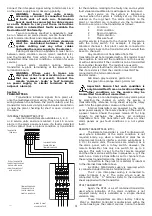
Incoming Signal fault.
If this fault is present on all panels on the
system, using an analoge voltmeter on a 10 volt DC
range, measure the voltage across terminals 1 & 2 on
the central panel. If no voltage is present, disconnect the
signal wiring from terminals 1&2 on the central panel
and repeat the test. If a voltage of between about 2-8
volts is now present then a short circuit exists on the
signal wiring or a repeater panel has been wired with the
signal wires reversed (check the polarity of the wiring
with the meter with the signal wires disconnected from
the repeater. Number 1 should be positive).
Reconnect the central panel and disconnect each
part of the signal wiring until the fault clears. The last
part of the wiring to be disconnected has the fault on it.
If no voltage was present at the central panel
after disconnecting the signal wires,
rst ensure that the
panel is set to be a central. If it is then
t a service
exchange board (Remember. A board can be “borrowed”
from another, less critical, location and used to get a
system running).
If the system fault only appears on one section of
the system, look for a broken wire or loose terminal
between the section with the system fault and the rest of
the system.
Contact Line fault.
This indicates that the wiring between the
transmitter in the alarm panel showing the system fault,
and the termination board is open or short circuit. A
service fault will be showing at the same time. This fault
(or faults) indicates which cable has the problem on it.
e.g. if a panel is showing a number 4 system fault and
say, pressure fault on nitrous oxide, the cable connected
to condition 4 on the nitrous oxide service on the
transmitter is broken or shorted to common or earth.
Note that unused inputs to transmitters must be
connected to common with a resistor to prevent a
system fault (see Transmitter section).
On Remote Transmitters and Plant To Alarm
Interfaces a 5mm round yellow LED provides warning for
a contact Line Fault when present at that transmitter.
Power Failure.
Check that the mains supply is sound. If sound,
check the fuses on the power supply board and replace
as necessary. If sound,
t service exchange boards.
IMPORTANT NOTE. If any control or
transmitter boards are replaced, ensure
that the replacement boards are set for the
correct channels. Carry out anti-confusion
tests when work is complete.
7
Appendix A - Cable types
Use only the following types of cable for wiring the alarm system:-
SWA
Overall screened cable
Single core cable in steel conduit. Must not contain any other cables.
A minimum cable size of 0.5 sq.mm is recommended. Solid cable such as telephone cable should NOT be used.
Continuity of screen, armouring or conduit must be maintained at all times. Particular
attention should be given to plastic junction boxes. Multicore cables must not be shared with
other systems.
Appendix B - System Faults
0. . . . . No fault
1. . . . . Incoming signal fault
2. . . . . Power failure
3. . . . . Incoming signal and power faults
4. . . . . Contact line fault
5. . . . . Contact line and incoming signal faults
6. . . . . Contact line and power faults
7. . . . . Contact line, power&incoming signal faults
8. . . . . Flashing circuit failed
9. .
Flashing circuit&incoming signal faults