


Connect the inter-panel signal wiring to terminals 1 & 2
on the power supply board, observing polarity.
WARNING. Ensure that cable screen,
armouring or conduit is connected to earth
at both ends of each run. Termination
boards must be connected to cable screens
or earth. Failure to carry out these instructions
WILL result in intermittent faults invalidate the
Declaration Of Conformity.
Two core cable as speci
ed in appendix A, must
be run between all alarm panels, remote transmitters,
plant to alarm interfaces and computer interfaces.
WARNING. A minimum of 20mm clearance
must be maintained between the alarm
system cabling and any other cables
(including the mains supply to the alarms).
Cabling as speci
ed in appendix A must be run
between alarm condition source (plant, manifold etc.)
and the transmitter from which the service is to be
transmitted. (One core per con common for each
service).
Connect alarm condition cabling between
transmitter & plant, terminating at the plant with a
termination board.
WARNING. Where over 5 Gases are
displayed at the Central location (i.e. more
that one panel is present). Connect the
remote 'common', 'mute' & 'test' terminals
on power supply, to similar terminals in the
adjacent alarm(s).
Section 4
TRANSMITTERS
Transmitters introduce signals from plant etc.
onto the multiplexed signal wiring. They also monitor the
wiring between the between the plant contacts and the
transmitter terminals via termination boards mounted in
or near the plant, checking for short or open circuits of
the cable.
INTERNAL TRANSMITTERS (ITX)
Internal transmitters are available as 1, 2, 3
or 4 service units and are mounted, 1 per 1-5 service
alarm, in the alarm panel enclosure. If a fault is detected
on the contact lines, an alarm condition is transmitted
for the condition relating to the faulty line, and a system
fault visual and audible alarm will appear on this panel.
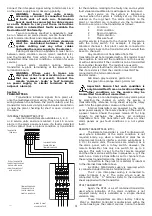
Each service on the system is allocated a
channel when the system is initially set up, this being
entered on the log sheet. The alarm contacts on the
plant or manifold are connected via the termination
board to a service on the transmitter as follows:-
C
Common
1
First condition
2
Second condition
3
Third condition
4
Pressure fault
and this service is then set to the channel for this service
with the rotary switch. For example, if Oxygen is
allocated channel 1, this plant could be connected to
service A terminals on the transmitter, which would then
be set to channel 1.
Any condition not transmitted from this
transmitter must be terminated with a 56k resistor to set
the condition to normal if the condition is not to be used,
or with a 1k8 resistor if the condition is to be transmitted
from another transmitter. The resistors are used to
prevent a system fault due to short or open circuit. Note
that if a resistor is
tted, the condition must NOT be
connected to the termination board.
Resistor codes:-
1k8 brown grey red silver, gold or red
56k green blue orange silver, gold or red
Important. Ensure that each condition is
only transmitted from one location although
other conditions on the service may be
transmitted from other transmitters.
Any service can be displayed on any alarm panel
by selecting the channel on which the service is
transmitted (by reference to log sheet) using the rotary
switch for the appropriate column on the alarm.
Internal transmitters are powered by the alarm
panel power supply or the reserve battery in the event of
a power failure. Should the power remain o
for long
enough to discharge the battery, all conditions
transmitted from this transmitter will show on other
alarm panels as gas fault conditions (i.e. not system
fault).
REMOTE TRANSMITTERS (RTX).
The Remote transmitter is a self contained unit,
used where indication of the alarm condition is not
required locally, e.g. when a manifold or plant has an
integral plant to alarm interface, and are available as 1,
2, 3 or 4 service units. The services are selected, as in
the alarm panel, with a rotary switch. However, the
remote transmitter has only one switch for up to 4
services. This switch is set to the
rst service required
and the other services will follow in sequence. e.g. if the
switch on a 3 service transmitter is set to channel 2 then
the services transmitted will be channels 2, 3 & 4.
Connection to the plant (or manifold) is identical
to the internal transmitter above.
A 230Vac, 50/60 Hertz supply is required, which
is connected under the mains terminal cover.
The 2 core inter-panel wiring is connected to
signal terminals 1 & 2. The cable screen must be
connected to the ``S'' terminal. Refer to the instruction
sheet supplied with the transmitter.
RTX1 TRANSMITTER
Again, the RTX1 is a self contained transmitter,
used where indication of the alarm condition is not
required locally and is available as a single channel
variation only.
These transmitters are often factory
tted by
Plant or Manifold Controller manufacturers within the
same housing as the contact sources, hence the board
C
1
2
3
4
SERVICE A
C
1
SER
C
C
1
1
2
2
3
3
4
4
TO ALARM
TO PLANT
CABLING BETWEEN
TRANSMITTER AND
TERMINATION BOARD
TERMINATION BOARD.
TO BE MOUNTED IN
CONTROL PANEL ON
PLANT OR MANIFOLD.
WIRING TO PLANT
ALARM CONTACTS
SDXPIC3
TRANSMITTER
TYPICAL TRANSMITTER
CONNECTIONS SHOWING
ONE UN-USED ALARM
CONDITION LINKED OUT
WITH A RESISTOR
TERMINALS
4


