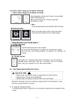
25
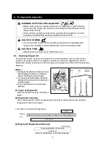
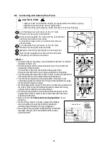
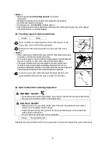
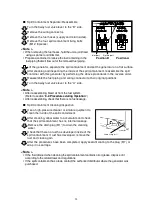
Turn the switches and breakers on the load side to OFF.
Turn the main breaker on the operation panel to OFF.
Turn the Throttle switch to IDLING.
The engine cools down for approximately three minutes.
Turn the starter switch to STOP.
9-4. Protective Functions
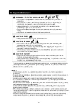
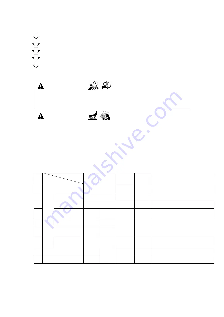
WARNING : INJURY
Do not open the check door during operation. Be careful of pinching or
catching of moving parts such as the cooling fan and fan belt.
Always be sure to stop the engine and remove the engine key when
performing inspection or maintenance.
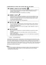
CAUTION : BURNS
Do not touch the engine and surrounding components immediately after
stopping the engine as they are still hot.
Hot steam gushes out from the coolant subtank if the generator overheats.
Do not touch the coolant subtank.
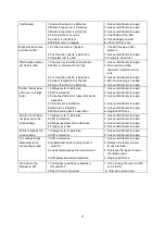
This generator is equipped with functions to automatically stop operation when there is a
fault/malfunction during operation, and one to warn the operator of the fault location by use
of indicator lamps. Check the fault location when the engine is automatically stopped or an
indicator lamp lights up to stop the engine.
Protection Feature List
No.
Action
Abnormality
ELCB
Trip
Breaker
Trip
Engine
Automatic
Shutdown
Warning
Lamp
Flash
Cause
1
M
o
n
it
o
r
L
a
m
p
High Water
Temperature
−
−
Activates due to high water temperature in
the engine
Default 115
℃
2
Low Oil
Pressure
−
−
Activate due to low oil pressure in the engine
Default
0.49
×
100 kPa
3
Battery Charge
Insufficient
−
−
Activates in battery charge Impossible
4
Engine
Overspeed
−
−
Engine speed is too fast
(2070 rpm or more)
5
Air Filter
Clogging Up
−
−
−
The element is clogged making it necessary
to clean or replace the element.
6
Spill Containment
Fluid Level
−
−
−
Spill containment accumulated fluid has
exceeded the specified level making it
necessary to flush the fluid.
7
Engine Malfunction
(
○
)
○
Water temperature is high, oil pressure is
low, battery voltage is low, engine
overspeeds, or some other engine fault
occurs during operation
8
Current Leakage
−
−
-
Activates in current leakage
9
Overload
−
−
−
Activates in overload
*
indicates the automatic activation.
1
2
3
4
5
Содержание DG50MK-P
Страница 2: ......
Страница 43: ...40 13 Generator Circuit Diagram...
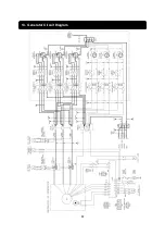
Страница 44: ...41 14 Engine Electrical Circuit Diagram...
Страница 45: ...42...
Страница 46: ...43...
Страница 47: ...44...
Страница 48: ...2016...


