6
Assembly
Mount the Cutting Attachment Shield on the
Gearcase
Remove the shaft bolt, bolt guard, holder A and holder B from the gearcase.
1.
Align the cutting attachment shield assembly (A) with the gearcase as shown,
2.
and then fit the shield onto the matching flange (B) on the gearcase.
WARNING!
The edger is intended for right-handed operation only! When cor-
rectly assembled, the cutting attachment shield and shaft must be oriented as
shown.
Install the socket-head screws (C) with washers. Firmly tighten all three
3.
screws.
Install a washer (D) and nut (E) on each of the three screws assembled in
4.
Step 3, then firmly tighten each nut.
IMPORTANT!
The three socket-head screws must be firmly tightened against the cutting attach-
ment shield before installing and tightening the nuts.
26019
A
S
S
E
M
B
L
Y
9
26018
26020
Mount the Edger Blade
1. Install the holder A onto the output
shaft. See Figure 6.
2. Mount the edger blade and holder
B onto the output shaft, and then
install the bolt guard and shaft bolt
(turn bolt counterclockwise to
install). See Figure 6.
3. Align the hole in holder A with the
matched hole in the gearcase, and
then use the hex wrench to
temporarily lock the output shaft.
See Figure 6.
4. Use the combination wrench to
firmly tighten the shaft bolt.
Remove the hex wrench.
See Figure 6.
WARNING!
n
The edger is designed for use
with an edger blade only!
n
Never operate the edger
without the cutting attachment
shield installed and tightly
secured!
Mount the Cutting Attachment
Shield on the Gearcase
1. Remove the shaft bolt, bolt guard,
holder A and holder B from the
gearcase. See Figure 5.
2. Align the cutting attachment shield
assembly with the gearcase as
shown, and then fit the shield onto
the matching flange on the
gearcase. See Figure 5.
WARNING!
The edger is intended for right-
handed operation only! When
correctly assembled, the cutting
attachment shield and shaft
must
be oriented as shown.
3. Install the socket-head screws with
washers, then use the hex wrench
to firmly tighten all three screws.
See Figure 6.
4. Install a washer and nut on each of
the three screws assembled in
Step 3, then firmly tighten each nut.
65010-94010_MLE230_07LP
11/21/01, 11:19 AM
10
A
B
C
D
E
M23004
A
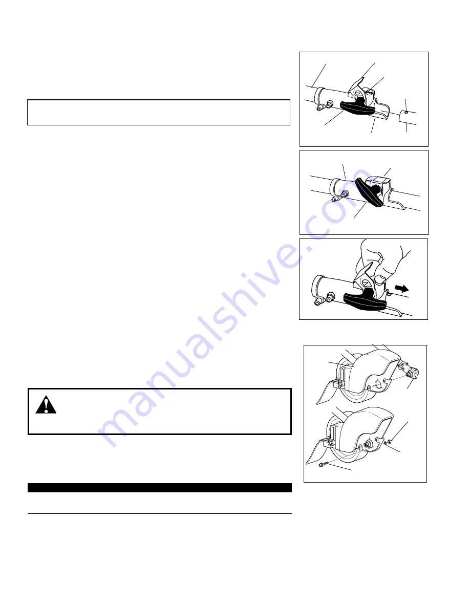
Place the Multipurpose Tool Carrier (A) and the Tool Assembly (B) on a clean,
1.
flat surface so that both assemblies fit end to end. The powerhead assembly
should be facing up, and the tool assembly should be positioned with the lock-
ing hole in the tube (C) end facing up.
CAUTION!
Keep the open ends of the tubes clean and free of Debris!
Slip off the protective cover from the end of the tool, and loosen the coupler
2.
screw knob (D).
Insert the tool assembly into the coupler (E), with the tool decal facing up, until
3.
the line of the decal is flush with the end of the coupler. Twist the tool back and
forth until you are sure it snaps in place by the coupler latch (F).
When the two tube halves are locked together, press down on the spring-
4.
loaded latch protector (G) and tighten the coupler screw knob.
Installing a Tool Attachment
M23005
G
D
E
M23006
B
C
D
E
F
G
Disassembling The Pole Sections
Place the Multipurpose Tool Carrier and the Tool Assembly on a clean, flat sur-
1.
face, loosen the coupler screw knob (D). The spring-loaded coupler protector
(G) should pop up.
Press down on the latch (F) with your finger or thumb. This releases the cou-
2.
pler latch.
Pull the tool assembly (B) out of the coupler (E).
3.
Содержание 65010
Страница 11: ...11...


