background image

Installation

 Installing the speed sensor

18


„

Installing the speed sensor

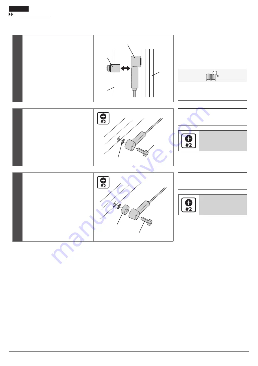
1

Before installing the speed sensor 

(A)

check that the clearance 

(a)

 between the 

speed sensor and the magnet unit 

(B)


will be within 3 to 17 mm.

(A)

(a)

(C)

(D)

(B)

(A) 

Speed sensor

(B) 

Magnet unit

(C) 

Spoke

(D) 

Chain stay

When checking the clearance is within 17 mm, 
take wheel truing, frame distortion, etc. into 
account.

2

If the clearance is within the designated 
range, place the toothed washer 

(E)


between the speed sensor and the chain 
stay, then attach the speed sensor fixing 
bolt 

(F)

.

(E)

(F)

(E) 

Toothed washer

(F) 

Speed sensor fixing bolt (16 mm)

Tightening torque:

1.5 - 2 N·m  
{14 - 17 in. lbs.}

3

If the clearance exceeds 17mm, use a 
spacer 

(G) 

to adjust it. Attach the speed 

sensor with the speed sensor fixing bolt 

(H)

.

(G)

(H)

(G) 

Spacer

(H) 

Speed sensor fixing bolt (22 mm)

Tightening torque:

1.5 - 2 N·m  
{14 - 17 in. lbs.}

Содержание BT-E6000

Страница 1: ... English DM SP0001 03 Dealer s Manual E6000 Series SC E6000 SW E6000 FC E6000 SM CRE60 DU E6000 DU E6001 SM DUE01 BT E6000 BT E6010 SM BME60 SM BME61 SM BCE60 TL FC38 ...

Страница 2: ... Installing the battery 17 Installing the speed sensor 18 Mounting the magnet 19 Installing and wiring the drive unit 21 Installing the drive unit 21 Drive unit wiring diagram 21 Connecting the power cord 22 Installing the ferrite core DU E6001 23 Connecting the electric wire 24 Connecting the assist switch and drive unit to the cycle computer 24 Connecting the speed sensor to the drive unit 25 Co...

Страница 3: ... and Setting 36 Names and functions of the parts of the assist switch 36 Basic screen display of the cycle computer 36 Launching and exiting the Setting menu 40 Changing the settings 41 Error messages on the cycle computer 48 Connection and communication with the PC 51 Settings customizable in E tube Project 52 Connecting to the PC 53 MAINTENANCE 56 Replacing the front chainring 56 ...

Страница 4: ...instruction manuals can be viewed on line on our website http si shimano com Please observe the appropriate rules and regulations of the country state or region in which you conduct your business as a dealer For safety be sure to read this dealer s manual thoroughly before use and follow it for correct use The following instructions must be observed at all times in order to prevent personal injury...

Страница 5: ...als when installing the product It is recommended that you use only genuine Shimano parts If parts such as bolts and nuts become loose or damaged the bicycle may suddenly fall over which may cause serious injury In addition if adjustments are not carried out correctly problems may occur and the bicycle may suddenly fall over which may cause serious injury Be sure to wear safety glasses or goggles ...

Страница 6: ...c shock may result Be sure to follow the instructions provided in the manuals when installing the product It is recommended that you use only genuine Shimano parts If bolts and nuts become loose or the product is damaged the bicycle may suddenly fall over resulting in a serious injury Maintenance interval depends on the usage and riding circumstances Clean regularly the chain with an appropriate c...

Страница 7: ...d plastic cover If you have any questions about the use and maintenance of the product consult the dealer where you made the purchase Products are not guaranteed against natural wear and deterioration from normal use and aging For maximum performance we highly recommend Shimano lubricants and maintenance products Contact the place of purchase for updates of the component software The most up to da...

Страница 8: ...Installation ...

Страница 9: ...case 3 mm Allen key Key unit cover Mount upper case Screwdriver 1 Speed sensor Speed sensor fixing bolt Screwdriver 2 Magnet unit Mounting screw Screwdriver 2 Electric wire Connector TL EW02 Light adapter Unit fixing screw Screwdriver 2 Drive Unit Frame installation bolt M8 bolt and nut compatible Cover fixing bolt M3 Screwdriver 2 Front chainring Lock ring TL FC32 36 TL FC38 Crank arm Crank insta...

Страница 10: ...inring SM CRE60 D Crank arm FC E6000 E Drive Unit DU E6000 E6001 F Speed sensor DU E6000 E6001 G Battery BT E6000 H Battery Mount SM BME60 I Battery charger SM BCE60 J Light adapter SM DUE01 K Drive unit cover SM DUE60 L Battery BT E6010 M Battery Mount SM BME61 Wire harness E tube Maximum cable length EW SD50 a 1600 mm A a B F C H G E D I J K BT E6010 SM BME61 L M ...

Страница 11: ... manual for the ALFINE S705 series Maximum cable length EW SD50 a 1600 mm b 700 mm Product specifications Operating temperature range During discharge 10 50 C Nominal capacity 11 6 Ah Operating temperature range During charging 0 40 C Rated voltage 36 V DC Storage temperature 20 70 C Drive unit type Midship Storage temperature Battery 20 60 C Motor type Brush less DC Charging voltage 100 240 V AC ...

Страница 12: ...hten the handlebar fixing bolt A with a screwdriver A B C A Handlebar fixing bolt B Clamp C Adapter Handlebar compatibility table øA øB øA Adapter Fixing bolt ø23 4 ø24 0 1 1 X 15 5mm ø24 ø25 5 0 1 1 X 20mm ø31 3 ø31 9 0 0 6 20mm X OK Handlebar øA øB 25 30 When removing the cycle computer reverse the procedure Tightening torque 1 N m 9 in lbs ...

Страница 13: ...e computer slide it while pushing the bracket lever C C C Lever NOTE If the cycle computer is not in the correct place the assist function will not operate normally Adjusting the angle of the cycle computer Loosen the angle adjustment screw A with a screwdriver Adjust the angle of the cycle computer to make it easier to see while riding After determining the angle tighten the screw to the designat...

Страница 14: ...ebar A A Cable band The cable band is included in SW E6000 2 Attach the assist switch mounted with the cable band to the handlebar Installing the assist switch 1 Attach the assist switch to a ɸ 22 2 handlebar with the electric wire routed under the switch and open the fixing bolt cover A B A A Fixing bolt cover B Fixing bolt 2 Tighten the fixing bolt B with a screwdriver 2 When removing the cycle ...

Страница 15: ...ist switch and that of the cycle computer E to the brake outer casing using F the band G and connect the electric wire of the assist switch to the cycle computer E F G E Electric wire of the cycle computer F Brake outer casing G Band The band is included in SC E6000 Installing the battery mount SM BME60 Align the mounting holes in the carrier with those in the battery mount Insert hexagon socket h...

Страница 16: ...shown in the illustration Temporarily attach the key unit cover and perform adjustment to make sure that the battery can be smoothly connected and disconnected and no noise will be produced due to looseness during traveling Then fully tighten the key unit fixing bolts 223mm a b Tightening torque 3 N m 27 in lbs 3 Fully tighten the key unit cover fixing bolts J to attach the key unit cover I Insert...

Страница 17: ... falling off check to see that the battery is locked after installation BT E6010 SM BME61 1 Align the indentation in the bottom of the battery with the protrusion on the mount and insert the battery 2 Slide the battery to the right starting from the point where it is inserted Push it firmly into place NOTE To prevent the battery from falling off check to see that the battery is locked after instal...

Страница 18: ...take wheel truing frame distortion etc into account 2 If the clearance is within the designated range place the toothed washer E between the speed sensor and the chain stay then attach the speed sensor fixing bolt F E F E Toothed washer F Speed sensor fixing bolt 16 mm Tightening torque 1 5 2 N m 14 17 in lbs 3 If the clearance exceeds 17mm use a spacer G to adjust it Attach the speed sensor with ...

Страница 19: ...ts center is aligned over the apex of the triangle symbol How to mount the magnet 1 Align the speed sensor A and magnet unit B as shown in the illustration A C B A Speed sensor B Magnet unit C Spoke 2 Tighten the mounting screw D with a screwdriver D D Mounting screw Tightening torque 1 5 2 N m 14 17 in lbs ...

Страница 20: ...Installing and wiring the drive unit ...

Страница 21: ...h Shimano products Use those supplied by the manufacturer For information on the tightening torques contact the manufacturer Drive unit wiring diagram Below is an example of wiring on a carrier type battery B A C D A Light connector B Speed sensor connector C E tube connector for cycle computers and motor units D Ferrite core NOTE Be sure to attach dummy plugs to any unused ports The left illustra...

Страница 22: ... arrow on the power cord connector A with the triangle symbol on the drive unit receptacle B and insert the power cord Insert it until it locks into place A B A Power cord connector B Drive unit receptacle Disconnecting from the drive unit To remove the power cord hold it by the grooved part of its end and pull it towards yourself ...

Страница 23: ...te core B Power cord 2 Make sure that the power cord is not pinched and firmly secure the ferrite core Then fix the ferrite core with the zip tie C C C Zip tie NOTE Check that the ferrite core tabs are firmly secured Do not cut off the excess portion of the zip tie The cut surface of the zip tie may scratch the cable or case Do not drop the ferrite core or subject it to any shocks Subjecting the f...

Страница 24: ...tric wire When installing the electric wire do not forcibly bend the plug It may result in a poor contact When connecting the electric wire push it in until it clicks in place Connecting the assist switch and drive unit to the cycle computer Use the TL EW02 D for connection A Cycle computers B Assist Shift switch C Drive Unit D TL EW02 The electric wire connector can be connected to any port of th...

Страница 25: ...peed sensor connector B using the TL EW02 A A TL EW02 B Speed sensor connector A B Connecting the light adapter to the drive unit To connect the light using the light adapter carry out wiring as follows A A Light adapter 1 Attach the light adapter A in the direction shown in the illustration Secure it to the drive unit with the unit fixing screw B A B A Light adapter B Unit fixing screw Tightening...

Страница 26: ...d tail light cables through the cable holes D shown in the illustration and attach the cover Tighten the cover fixing bolts E in the three locations E D D Cable holes E Cover fixing bolt M3 Tightening torque 0 6 N m 5 3 in lbs 5 Fix the light cables to the electric wire around the light adapter and route them along the frame G F F Front light cable G Taillight cable For information on compatible l...

Страница 27: ...W SD50 for cycle computer 2 Make sure that the electric wires are not pinched and firmly secure the ferrite core Then fix the ferrite core with the zip tie D The zip ties are included with MU S705 D D Zip tie NOTE Check that the ferrite core tabs are firmly secured Do not cut off the excess portion of the zip tie The cut surface of the zip tie may scratch the cable or case Do not drop the ferrite ...

Страница 28: ...C 14 mm socket wrench Tightening torque 35 50 N m 306 437 in lbs 3 Align the cutout in the front chainring D with the wide area F on the chainring installation part E when inserting the front chainring In the case of DU E6000 When installing a front chainring labeled SM CRE60 a spacer needs to be placed between the front chainring and the chainring installation part In the case of DU E6001 This ca...

Страница 29: ...read Tightening torque 35 45 N m 306 393 in lbs 5 Insert the right crank arm attach the crank arm fixing bolt and tighten it Finally attach the crank arm cap Tightening torque 35 50 N m 306 437 in lbs 6 After installing the crank arm turn the crank counterclockwise to make sure that the crank rotates smoothly Adjustment of the chain tension When using an internal geared hub it is necessary to adju...

Страница 30: ...Charging the battery ...

Страница 31: ...arged at the time of shipment Before riding be sure to charge the battery until it is fully charged If you will not use the bicycle for an extended period of time charge the battery before storing the bicycle If the battery has become completely discharged charge it as soon as possible If you leave the battery uncharged the battery may deteriorate If you will not ride the bicycle for an extended p...

Страница 32: ...nected 1 hour or more after the completion of charging E F E Charger LED lamp F Battery level lamp DANGER Use the battery and charger combination specified by the company for charging and follow the charging conditions specified by the company Not doing so may cause overheating bursting or ignition of the battery NOTE If the bicycle is stored for an extended period of time immediately after purcha...

Страница 33: ...Lighting up Blinking Indication when the battery is not connected to the charger or bicycle Battery level indicator 1 Battery level 100 81 80 61 60 41 40 21 20 1 0 Power off Shutdown 1 No light Lighting up Blinking Indication when the battery is connected to the bicycle When the battery is turned on all the indicators turn on To find out the battery level check the Cycle Computer display ...

Страница 34: ...ontact an agency Security authentication error This is displayed if a genuine drive unit is not connected This is displayed if any of the cables are disconnected Connect a genuine battery and drive unit Check the condition of the cables If the situation does not improve contact an agency Charging error This is displayed if an error occurs during charging Remove the connector between the battery an...

Страница 35: ...Cycle Computer Display and Setting ...

Страница 36: ...edaling becomes heavier Z When switching assist modes the level of assistance becomes weaker When shifting gears pedaling becomes lighter X Y Z Basic screen display of the cycle computer A D B C E F A Speed Displays the current speed B Clock Displays the current time C Speed unit display You can switch between km h and mph D Battery level indicator E Changing the assist mode display F Gear and tra...

Страница 37: ...or 2 seconds switches to the walk assist mode Press Assist Y to switch the mode to OFF Assist Shift Pressing and holding down When WALK is displayed press and hold down Assist Z on the assist switch to start the walk assist function Releasing Assist Z stops the walk assist function or pressing Assist Y can stop the walk assist function NOTE When WALK is displayed the mode changes to OFF if Assist ...

Страница 38: ...ted Start gear 4 when setting start mode Traveling distance Cumulative distance Maximum traveling distance 1 3 Maximum traveling distance optional 2 Traveling time optional 2 Average speed optional 2 Maximum speed optional 2 1 The battery level in D and walk assistance in E are not displayed when RANGE is displayed The traveling range should be used as a reference only 2 Optional item You can conf...

Страница 39: ...is off the light is off Clearing the traveling distance When the light is not connected you can clear the traveling distance in the main screen If a light adapter is connected and configured clear the traveling distance DST according to Changing the settings Clear settings Clear 1 Assist Shift 2 seconds Change the traveling data display to DST and press the Assist X button for 2 seconds 2 Assist S...

Страница 40: ...re Pressing the Assist X button displays the setting screen for the item selected Assist Assist Clear Clock Exit Start mode Adjust Backlight Language Beep Unit Item Details Clear Clear settings Clock Clock setting Start mode Start mode setting Backlight Backlight setting Beep Beep setting Unit Switching between km and mile Language Language setting Adjust Adjusting the power gear shifting unit Exi...

Страница 41: ...r Assist Z to switch between OK and CANCEL 4 3 Press Assist X Selecting OK validates a setting while selecting CANCEL cancels the setting after which the screen returns to the Setting menu Assist Shift The settings have a range of 4 to 4 Confirmation and fine tuning of gear shifting CAUTION Improperly large adjustment may cause free spinning of the pedals during pedaling resulting in an accidental...

Страница 42: ... has improved Assist Shift 3 The condition has improved Adjust the adjustment value by 1 speed in the same direction and check the gear shifting operation again Repeat these steps until any noise or unusual feeling disappears 1 2 3 No apparent change Adjust the adjustment value by 1 speed in the same direction and check the gear shifting operation again If the condition has improved see The condit...

Страница 43: ...al feeling is gone 1 1 4 Finally go for an actual ride and check for any noise or unusual feeling If the adjustment value is not 0 1 Assist Shift Press Shift Y or Shift Z and revert the adjustment value to 0 4 0 2 Press Assist X Select OK then perform an actual gear shift to check whether the condition has improved If there is any noise or unusual feeling see If the adjustment value is 0 to contin...

Страница 44: ...sh Italian 2 Pressing the Assist X button enables the set value and takes you back to the Setting menu screen Assist Shift Switching between km and mile Unit Configure the distance unit setting 1 Assist Shift Press the Assist Y or Assist Z button to move the cursor to the item you want to configure Item Details km Displayed in km mile Displayed in miles 2 Pressing the Assist X button enables the s...

Страница 45: ...tton enables the set value at the cursor position and takes you back to the Setting menu screen Assist Shift Backlight setting Backlight Configure the backlight setting 1 Assist Shift Press the Assist Y or Assist Z button to move the cursor to the item you want to configure Item Details ON Always turned on OFF Always turned off MANUAL Turns on and off in conjunction with the battery powered light ...

Страница 46: ...o the Setting menu screen Assist Shift Clock setting Clock Configure the clock setting 1 Assist Shift Press the Assist Y or Assist Z button to adjust the time Press Assist Y to increase the time value Press Assist Z to decrease the time value 2 Assist Shift Pressing the Assist X button enables the set value and moves you to the minutes setting 3 Press the Assist Y or Assist Z button to set the min...

Страница 47: ...re Item Details Exit Return to the Setting menu screen DST Clearing the traveling distance Default Reset the SC display setting to default Default value set in the SC display setting Item Default value Backlight ON Beep ON Unit km Language English 2 Assist Shift Pressing the Assist X button enables the set value at the cursor position and takes you back to the Setting menu screen When the travelin...

Страница 48: ...imum speed up to which power assistance is provided may decrease Power assistance is provided up to 25 km h in top gear Check that the speed sensor is properly installed If the situation does not improve consult an agency W030 Two or more assist switches are connected to the system Gear shifting is not available for power gear shifting derailleurs Change the assist switch to the gear shifting swit...

Страница 49: ... situation does not improve consult an agency E012 The initialization of the torque sensor failed Power assistance is not provided during riding With your foot off the pedal press the power switch of the battery to turn on the power again Refer to Adjustment of the chain tension then check that the chain tension is appropriate If the situation does not improve consult an agency E020 A communicatio...

Страница 50: ...Connection and communication with the PC ...

Страница 51: ...Project to configure SHIMANO STePS and update firmware Download E tube Project from our support website http e tubeproject shimano com For information on how to install an E tube project check the E tube support website For information on how to use E tube Project on your PC refer to the help manual for E tube Project NOTE You need SM PCE1 and SM JC40 JC41 to connect SHIMANO STePS to a PC They are...

Страница 52: ... position when on is selected Display monitor setting Display units Switches the display unit between km and mile Time setting Sets the time Backlight setting Switches the backlight of the cycle computer on or off Beep setting Switches the beep sound on or off Display language You can choose from English French German Dutch Spanish and Italian Traveling time Switches the traveling time indication ...

Страница 53: ...and communication with the PC Connecting to the PC 53 Connecting to the PC When connecting only individual units Connect SM PCE1 to the connector of each unit NOTE When connecting only SW E6000 you need SM JC40 41 ...

Страница 54: ...rt of the cycle computer A Assist switch B Drive Unit A B When the cycle computer has no available port 1 First connect SM JC40 JC41 to SM PCE1 Then disconnect EW SD50 from the center port of the cycle computer and connect it to SM JC40 JC41 A Assist switch B Drive Unit A A B 2 Connect EW SD50 to the available port of SM JC40 JC41 and the center port of the cycle computer ...

Страница 55: ...MAINTENANCE ...

Страница 56: ... TL FC11 2 While holding the wheel use the Shimano original tool to loosen the lock ring in the direction shown in the illustration A B A TL FC32 FC36 B TL FC38 TL FC38 NOTE If using a torque wrench use TL FC38 in combination with TL FC33 TL FC33 TL FC38 An impact wrench cannot be used The lock ring has a left hand thread 3 Replace the front chainring To install a front chainring refer to steps 3 ...

Страница 57: ...Please note specifications are subject to change for improvement without notice English Nov 2014 by Shimano Inc HTR ...

Отзывы: