


➟
Please copy this
information from the
CapStar
serial plate.
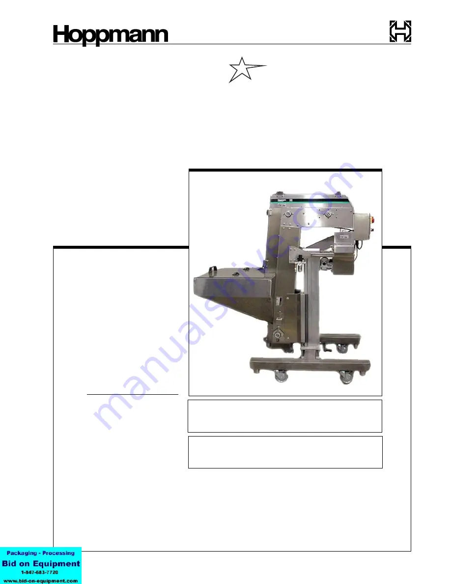
Cap Feeder
ANSI/Metric Installation
& Maintenance Manual
Refer all servicing to
qualified personnel.
This manual is intended
for use by qualified
mechanics and electricians
who install or service the
CapStar Cap Feeder
Inventory Number (Check One):
❑
FCCPSTLDSA
❑
FCCPSTRDSA
❑
FCCPSTLASM
❑
FCCPSTRASM
Cap
Star
First Edition, Publication Version, All Rights Reserved
Copyright © 2002 by Hoppmann Corporation.
15395 John Marshall Highway
Haymarket, VA 20169
Phone: (703) 753-8888
Toll Free: (800) 368-3582
Fax: (703) 753-7485
http://www.hoppmann.com
Inventory/Serial Number:


