


17
Remove the pump, connecting rod and bearing as de-
scribed on pages 14 and 16.
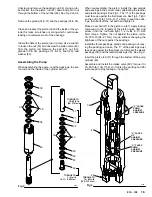
Remove the capscrews (25 & 68), lockwashers (24), and
drive housing (A). Remove the screws (66), lockwashers
(67), and motor housing (B). See Fig 6.
Clean and inspect the gear (69) for wear or damage. Re-
place it if necessary. To remove the gear, drive out the pin
(70), and pull it off the motor shaft. Apply molybdenum
disulfide spray lubricant to the new gear, allow to dry, then
apply industrial, heavy–duty extreme–pressure, lithium–
soap grease.
Install new drive assembly in reverse order of removal.
CAPACITOR
WARNING
To reduce the risk of serious bodily injury, including
fluid injection; splashing in the eyes or on the skin;
injury from moving parts or electric shock, always
follow the Pressure Relief Procedure Warning
on page 12 before continuing.
Unplug the sprayer. Remove the cover of the capacitor
(5). See Fig 7. Remove the flag connectors from the old
capacitor. Connect the flag connectors of the new capac-
itor and replace the cover.
NOTE: The replacement capacitor includes a new resis-
tor already installed.
ELECTRIC MOTOR
WARNING
To reduce the risk of serious bodily injury, including
fluid injection; splashing in the eyes or on the skin;
injury from moving parts or electric shock, always
follow the Pressure Relief Procedure Warning
on page 12 before continuing.
Disconnect the hose (20) from the nipple (22). See Fig 1.
Remove the drive assembly as described above. You
can leave the pump, connecting rod, and bearing as-
sembled to the drive assembly.
Drive out the pin (70) and remove the gear (69). See Fig
7.
Remove the screws (78) and the cover (79) from the
pressure control (74). See Fig 8.
Disconnect the five motor leads.
Unscrew the nuts on both ends of the conduit (76) from
the connector (75). Remove the screws (8), nuts (18) and
lockwashers (9). See Fig 7. Lift the motor (1) while care-
fully guiding the wires through the connector in the con-
trol box. Remove the conduit (76) from the wires.
Loosen the locknut and unscrew the connector (75) from
the motor, being careful to avoid twisting the wires.
Install the new motor in the reverse order of removal.
Fig 7
Fig 8
9
18
5
1
70
69
8
RED
BLACK
BROWN
WHITE
GREEN
76
75
75
79
PINK
BLACK
POWER
SUPPLY
LEADS
GREEN & YELLOW
MOTOR
LEADS
RED
WHITE
TRIAC
LEADS
1
74
WHITE


